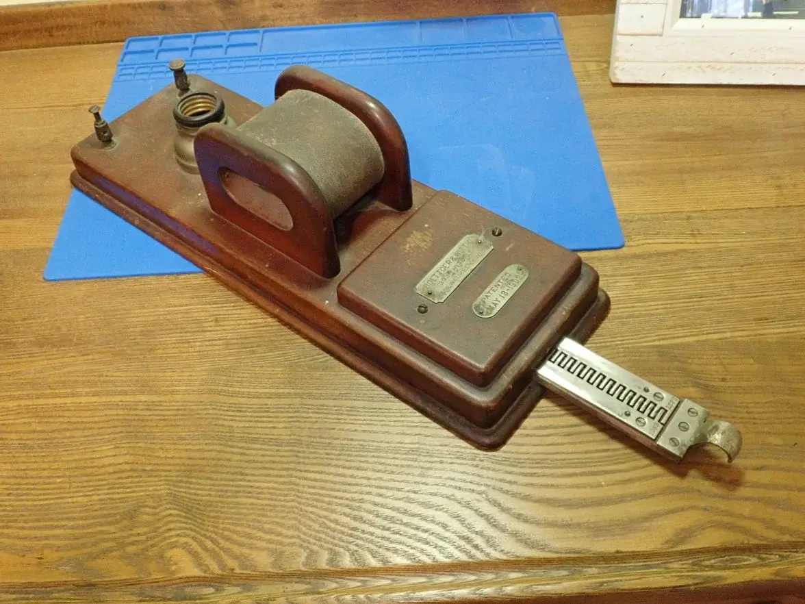
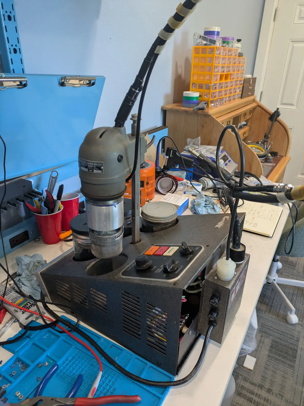
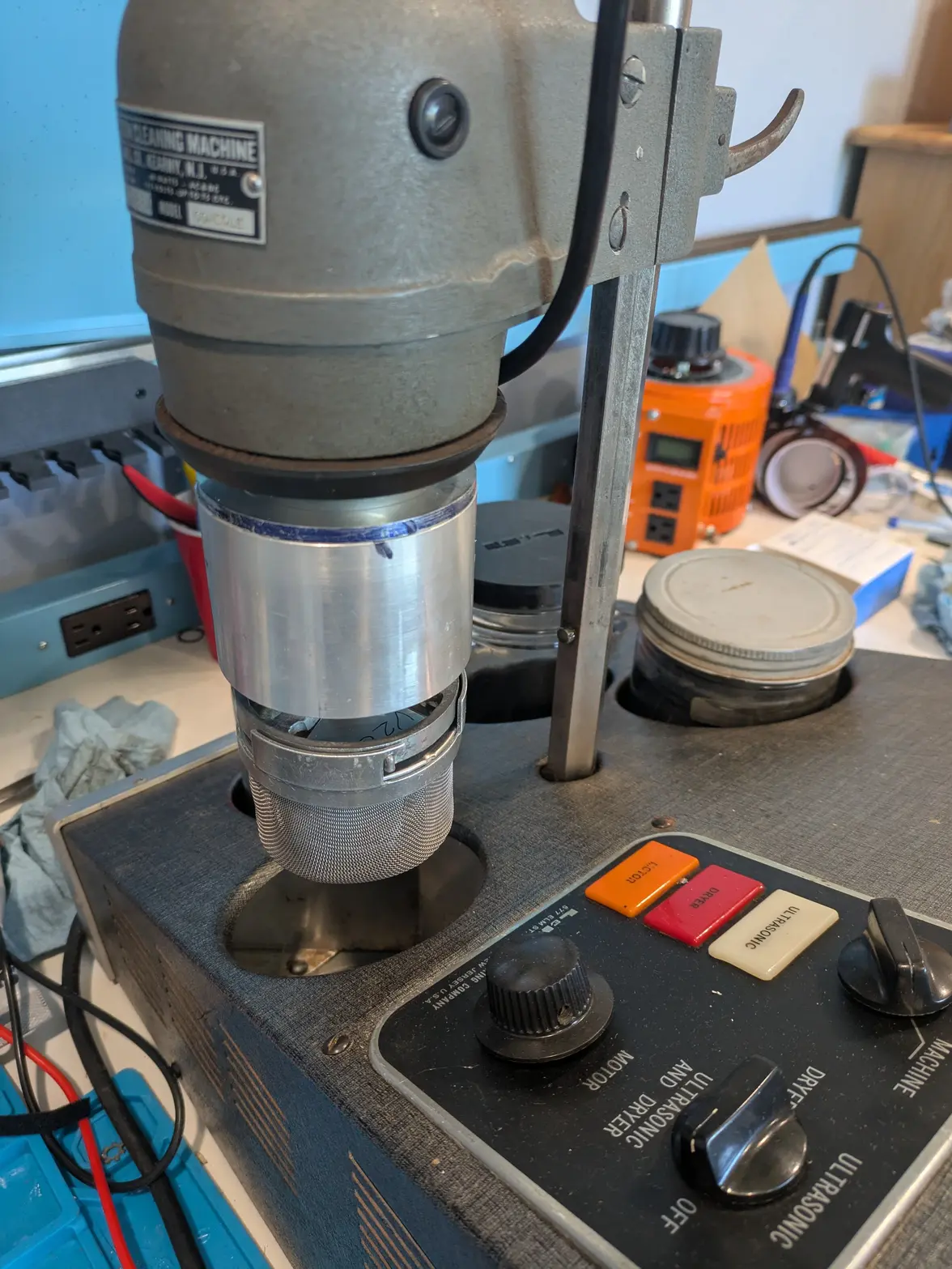
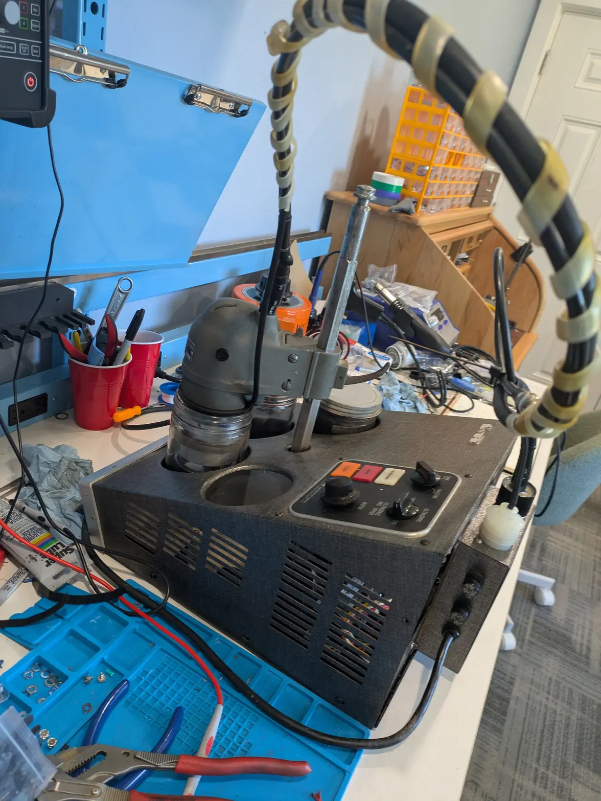
New(old)Tool day! L&R Console Watch Cleaning Machine

Posts
1,087
Likes
1,163
No good pictures today, but I got the whole transducer assembled and tried to test it. What you do do is have a signal generator run a sine wave through it and a resistor, then use the oscilloscope to measure the frequency input and the current-only (via the resistor) and see when the two line up/maximize the current use, which should be your point of resonation.

I can do this test pretty easily/predictably with the off-the-shelf transducers, they work fine.

However, I'm not really getting anything like that at a reasonable frequency (my measurement was 182khz!), and shortening it didn't seem to change much. So the 'horn'/'can' isn't really working as a resonating horn, and I'm not sure why. I tried shortening it a bunch (down to ~25.75mm horn, compared to 25mm-25.5mm of the commerical ones I picked up during this), and don't really get the behavior I'm expecting.

I'll probably have to spend a bunch more time on this. Alternatively, since the size is now 'about right', I might just hook it up to a driver board and see what happens.
 
Posts
1,087
Likes
1,163
So... I'm not dead yet 馃榾

I thought about the above failure for a while overnight, and realized that the piezos are frequency specific. I confirmed by shopping on AliExpress (the American dealer I bought the 40*20*5 ones from at a pretty outrageous MOQ/price didn't publish a frequency, which is why I didn't think about it!), and discovered that the rings sold from China list a frequency!

I wasn't able to figure out the relationship between size/material and frequency, but that is my guess.

SO I am re-encouraged to try harder to get the scavenged from 40khz transducer ones. I originally gave up because the 9/16-18 thread made too small of a wall.

BUT I am finding that the factory 1/2" bore was probably because it is a cast part, not because was needed. I thought I was cheating doing 12mm, but can probably go much closer to 11 mm on my next version.

Additionally I found that there exists a weirdo thread for suppressors (.578-28) that might be perfect, but it means tooling is cheap/easy to get. I'll have to decide whether it is worth the extra work to "just do it" vs making an adapter for a bolt instead馃榾

BUT family visiting, so whether I get shop time for another week is in the air.
 
Posts
1,087
Likes
1,163
FINALLY got some more shop time 馃榾 I took the week off to order a hunk of 416SS. I'd noticed that the ID of the center shaft had some rust spots, which I don't want to be a problem. I hoped the cold-blue would prevent this, but perhaps I didn't sufficiently cold-blue.

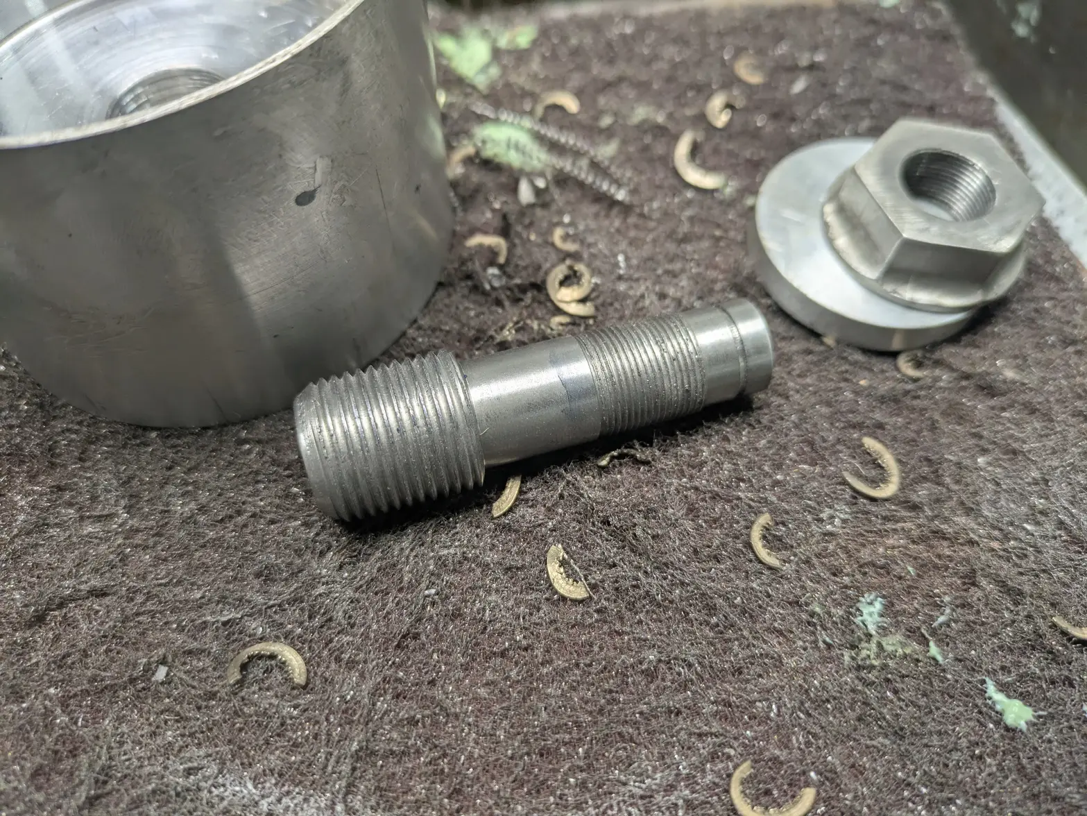
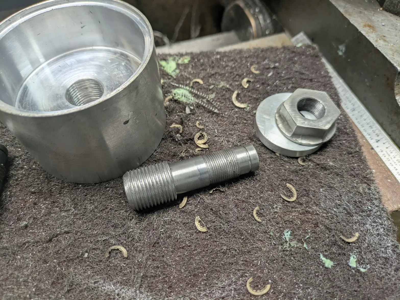
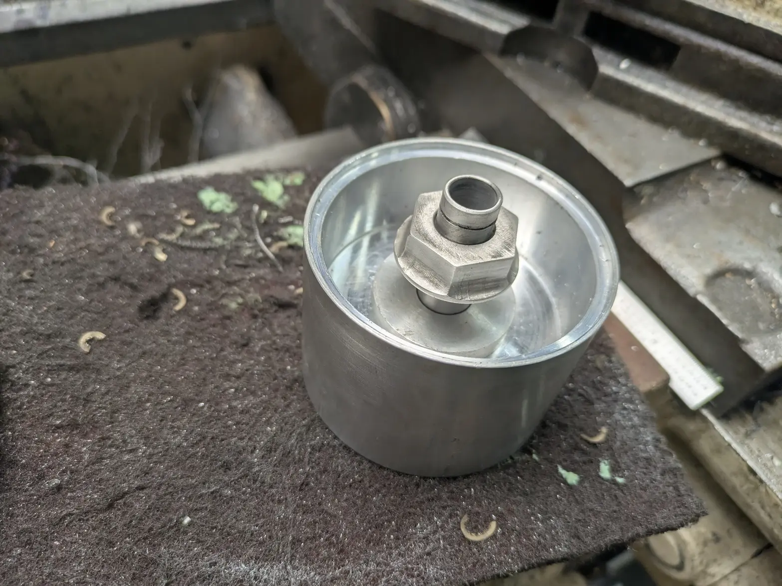
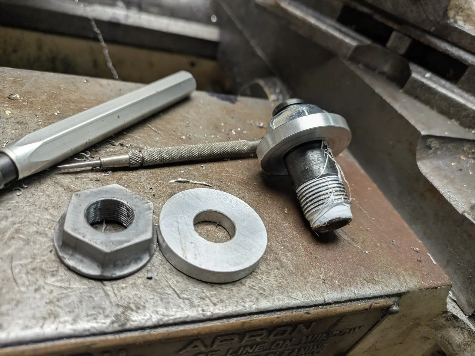
Last night I made the force distribution washer that goes under the nut, and the nut itself. The washer is probably not a big deal, but I don't want the nut riding on the piezo directly. I can perhaps lube between it to make tightening it down less adventurous.

Additionally, I made the nut. I made it a 1" hex with a flange to hopefully better distribute the load. As mentioned before it is a .578-28 thread, which I cut with a tap, rather than single-pointing. It was a giant PITA to get right, as I made it a little 'backwards' (I used a collet block on the mill to cut the hex, but put the extra material on the 'top' to make sure I had a 'flat' bottom).

However, 1 design change that I made intentionally: The top of the nut is 'flat'. Previously I was dealing with the commerical nut, which wasn't flat. I have to seal this surface against the cap to keep it water-tight, so I was trying to come up with ways to make this sufficiently water tight. By making it flat, I'll be able to use O-rings or RTV pretty trivially.

On the right of the picture is the old nut, washer, and center shaft out of mild steel. SO, I still have to make the new shaft, then I should be able to test this out.

 
Posts
3,544
Likes
8,103
Outstanding project for us seniors, seeing old things stage a comeback!
When your vintage workshop is ready, I've got a 100+ yr. old demagnetizer for you to sort out. You've proven your up to the challenge!
Thanks for the time spent sharing with us.
 
Posts
1,087
Likes
1,163
Outstanding project for us seniors, seeing old things stage a comeback!
When your vintage workshop is ready, I've got a 100+ yr. old demagnetizer for you to sort out. You've proven your up to the challenge!
Thanks for the time spent sharing with us.
Huh, neat! What is wrong with it? There isn't much that can go wrong on those I think, it is just a transformer? At worst, it'll need a re-wind (though I haven't done a rewind before!).
 
Posts
3,544
Likes
8,103
Can't say anything is wrong with it, researched the patent # years ago and thought it was very cool! Went no further.
Picture sliding that sucker in and out.
Probably the wet cell power source (picture Ben Franklin's acid filled glass jars with wires hanging out) scared me off. Got it when I bought my 1932 bench and had visions of becoming an old school watchmaker. Unfortunately, those times have passed.

Erich, please forgive me for any sidetrack or thread drift from a truly outstanding project that we are enjoying while we follow you!
 
Posts
1,087
Likes
1,163
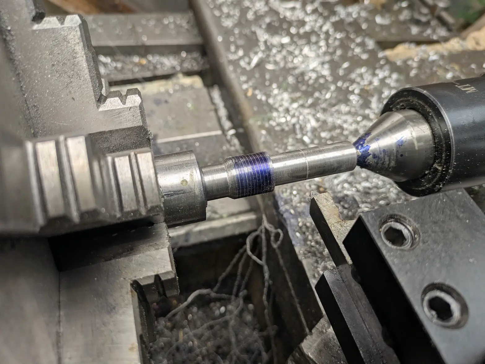
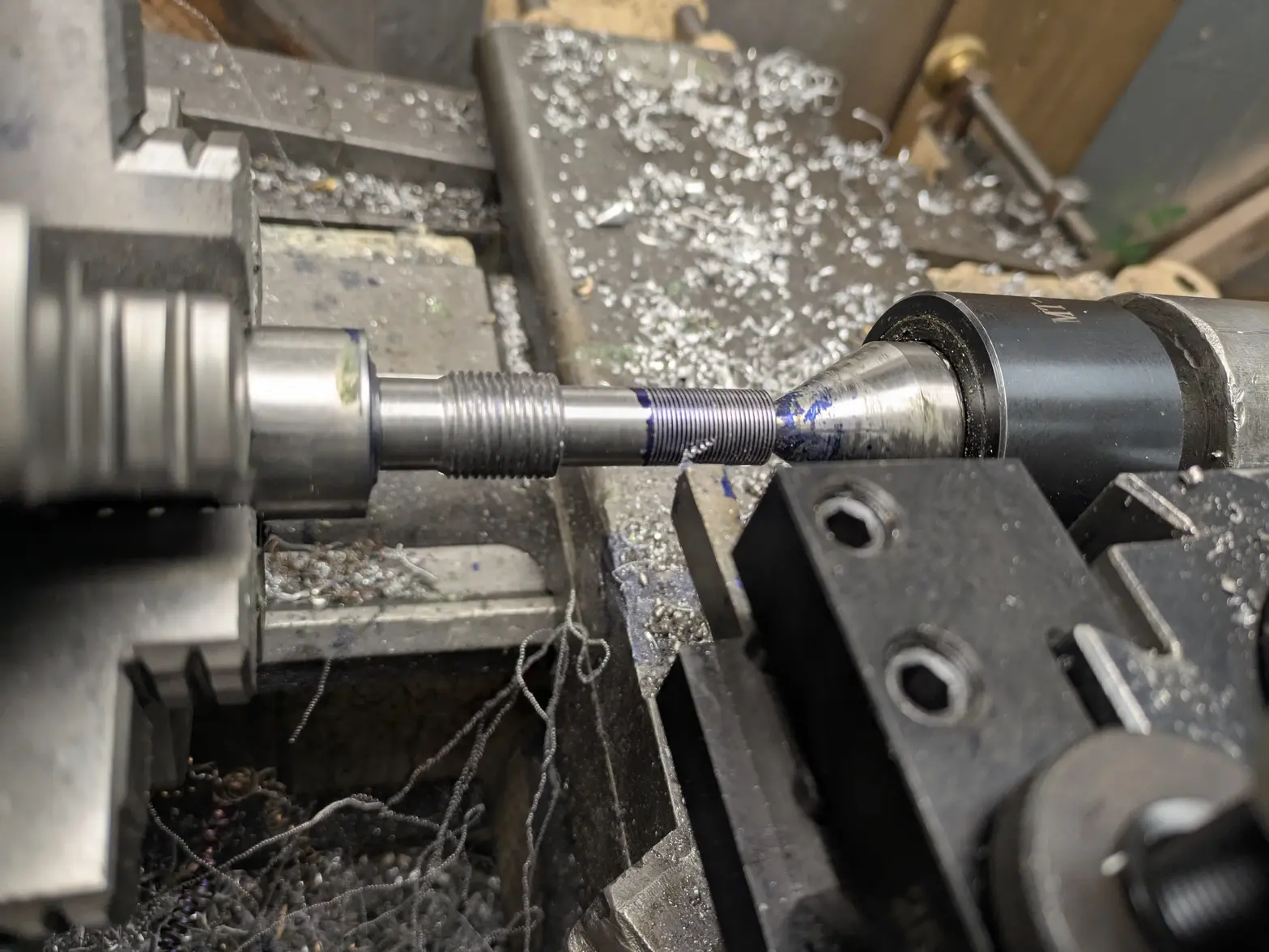
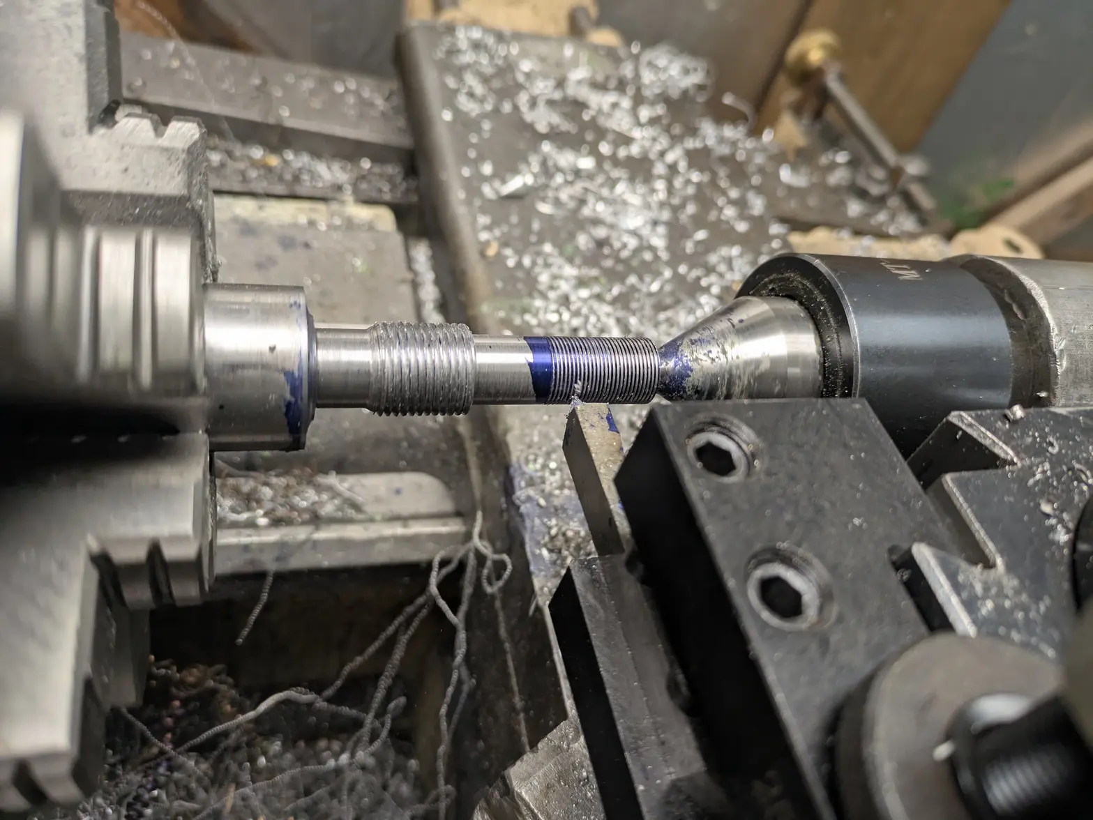
Alright, got a little afternoon shop time so I spent it making the center shaft.


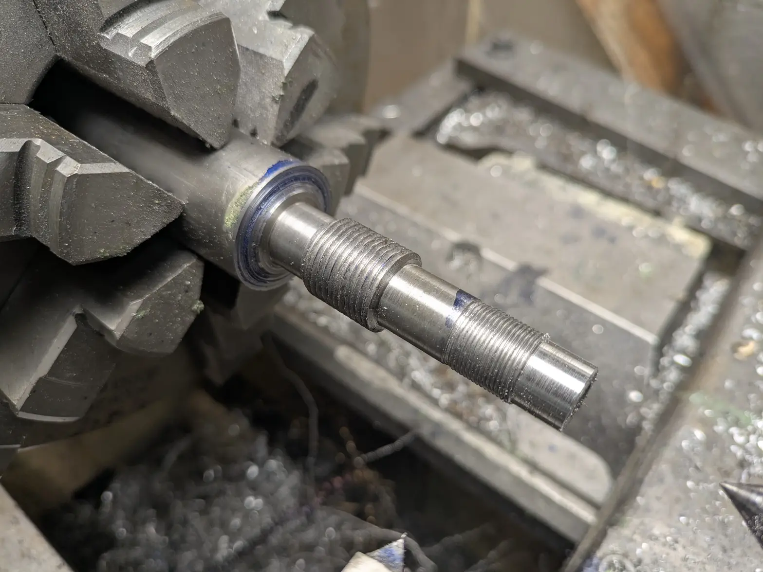
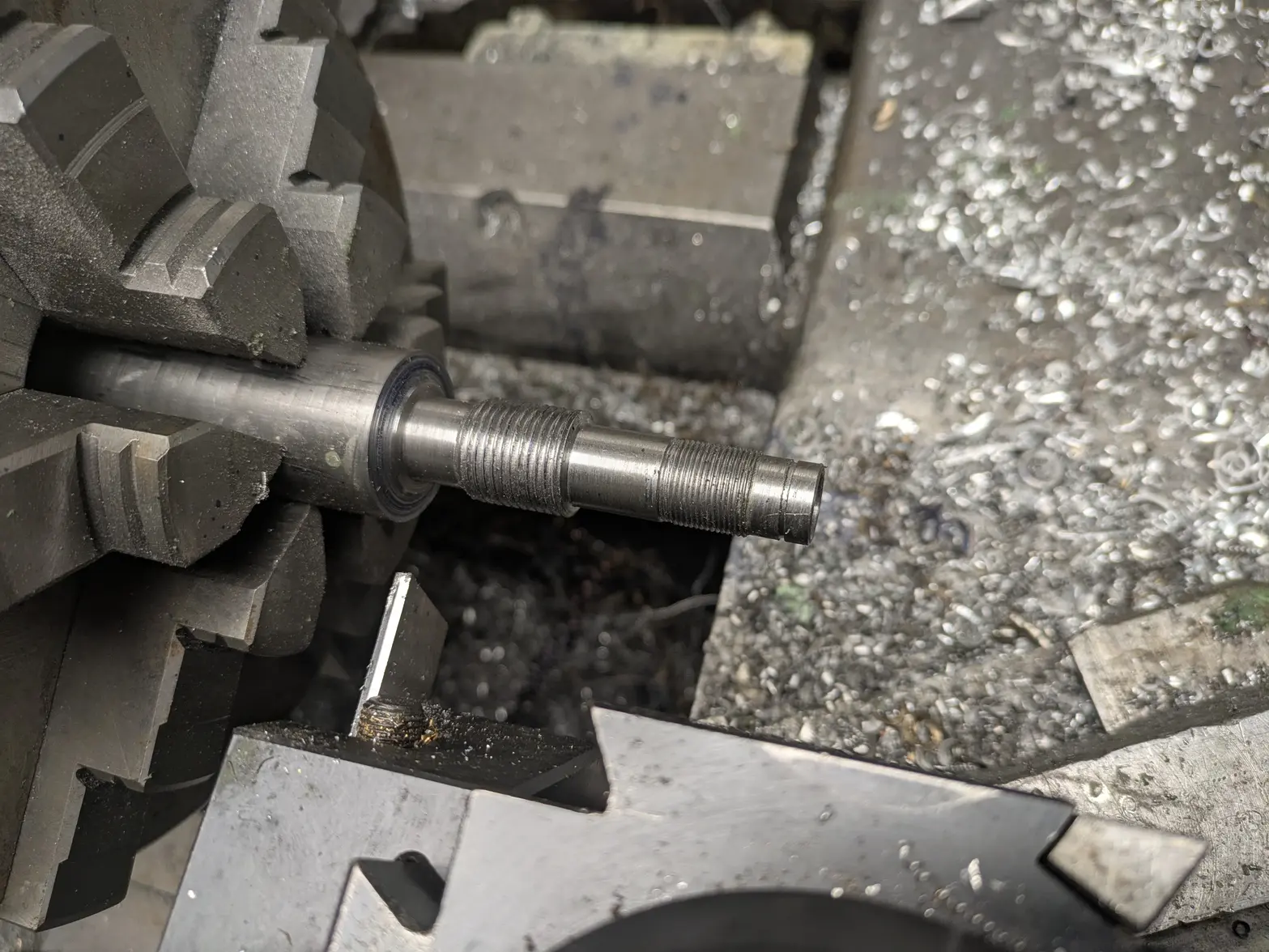
Some progress pictures 馃榾 all a single setup on the lathe from 416SS, though the 1.25" bar meant I had to remove a lot to get to 3/4. Also, got to single point both threads.


In the end, it was reasonably easy. I used a 27/64" drill bit for the center hole, which is ~10.7mm. I'm hopeful that is big enough, else I have to go onto the lathe and make it larger. I left a little more 3/4"-16 threads than last time, but that was without good reason.

One more thing I realized: The smaller shaft means I won't fill up the center hole in the cap, so I probably have an additional part to make to help keep the top on (just some sort of sealing bushing), but that is a problem for if this part works. I should be able to test in the next few days.
 
Posts
1,087
Likes
1,163
Urgh... I wanted to get the center post installed instead of paying attention in a meeting this morning. SO I did the Kapton tape along the center of the post[0]. My previous version used a smaller thread to attach to the aluminum horn/can, so I could just let it bottom out. However, since I didn't want to re-make the can, I have to loctite it in place (PLUS use some teflon tape to keep it water tight!). SO I was going to use the washer to help me make sure I get the height right.

BUUUT dummy me made the center hole of the washer at 14.93mm, so after tape, its too small. SO, I won't be able to test it until I enlarge the hole, the tool (I ordered a reamer, but maybe I'll come up with a different way in the meantime).

COMPLETE side note: The Varimatic with Ultrasonic that was on my local FB Marketplace (well... about a 90 minute drive) for CHEAP ($400!) sold finally. I told myself if it was still there after this project I'd HAVE to pick it up 馃榿 SO, someone saved me!


[0]: The way the transducer works: You have 2 ceramic piezos with the '+' sides facing eachother, and the positive terminal as a copper-sheet between them. The center shaft/other sides of the piezos/etc are all ground. SO you have to insulate the center post from the center contact/center of the piezos. Factory ones use a delrin tube 15mm OD, 10mm ID (for a 10mm bolt which is used as the clamp). I obviously cannot, since I need the shaft as large as possible, so I went with some Kapton tape around it. The piezos themselves don't have contacts on the inside/have a coating, so it is JUST the copper sheet that is vital to keep separated.
 
Posts
1,087
Likes
1,163
Ooof.... I'm shaking. I know these don't mean anything to anyone, and I'll come back in a bit to explain it, but in short: unbelievable success.

 
Posts
1,087
Likes
1,163
Alright, I needed to take a walk 馃榿 I had a down-15 minutes at work so I decided to test my transducer.

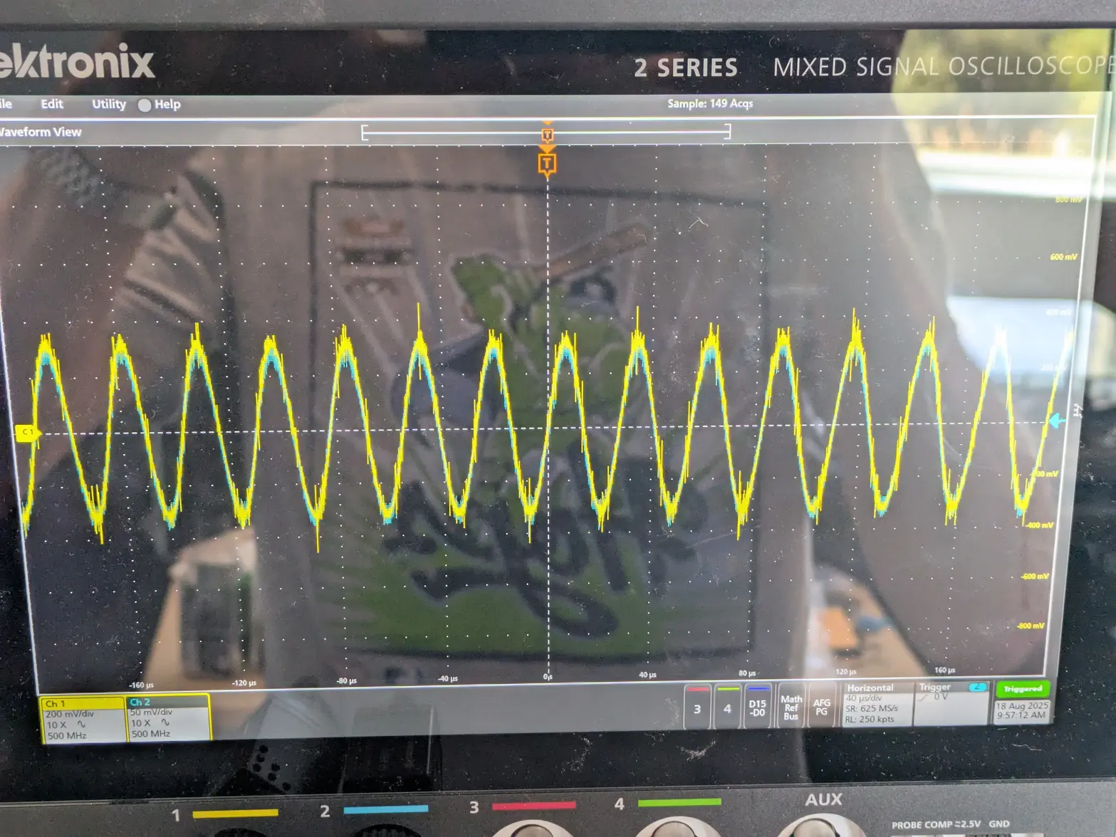
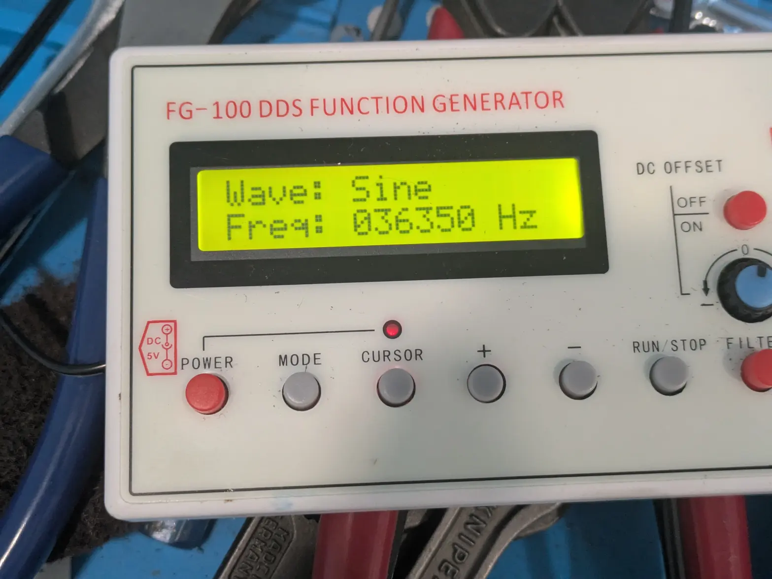
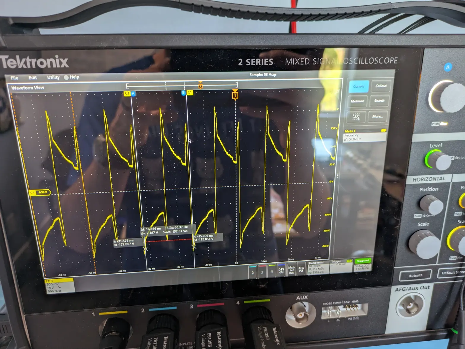
The way you test one of these is with an oscilloscope (pictured #1) and a frequency generator (#2). Note: I have 2nd frequency generator that makes it easier to get a less-accurate view, but has a non-calibrated handwheel that I used to get close (which is how the previous test worked).

BUT the test setup is this: You have 1 probe (yellow above)set to measure frequency directly, and 1 probe (blue above) to measure the current-draw across a resistor. You then run a frequency generator. If you're within a few hundred hertz, you will see the current draw start to show oscillations.

Your resonant frequency (and thus where it'll cause good cleaning) is when the two get back into phase, which is also the 'maximum' current draw.

What you see in the pictures above is my setup on the Oscilloscope. As you can see, the two lines align perfectly, with equal phase on BOTH, and the function generator at 36350hz. So my current resonant frequency is a little more than 36k.

What this means:

Frequency will get 'higher' as I shorten the horn. I'm at 25.75mm (I have 2 off-the-shelf ones, with horn lengths of 25mm and 25.25mm), so I have tons of room to tune this. I just have to pop it on the lathe and do some work!

BEFORE I get this on the lathe, I want to figure out the behavior of the driver boards that I have. My not-good-at-electronics brain THINKS they are going to oscillate wherever the transducer resonates naturally, as long as it is within a few hundred hz of 40khz. I want to confirm that, and if so, just aim for a perfect 40khz. IF not, I might do my best to aim for a range closer to whatever the driver generates.

Anyway, for the first time, I'm confident we've hit "success is both possible and probable". I still have a bit of work to do as I have to:

1- Tune the transducer by shortening the horn as mentioned above.
2- Finish sealing up the transducer, make sure it can run freely on the shaft, and mount it.
3- Figure out wiring to the machine. I've decided I want to get the 'factory' plugs working, but put a BNC connector in the middle. This simplifies wiring a little, but I have to get a non-crap BNC female connector on the factory wire 馃榾
4- Remove the entirety of the oscillation circuit from the machine.
5- Figure out how to mount the driver boards in the machine, I probably need to make a bracket or something.
6- Wire up the driver boards. I have a diagram drawn on a slightly-better-than-napkin on how to do this, but I have to re-figure out what the heck I was thinking 馃榾

BUT in the end, I think we're on the 'downhill' here! None of the above is an 'unknown' like this part was.
 
Posts
1,087
Likes
1,163
Awesome...... 馃榾

I'll try to do a better job explaining 馃榾

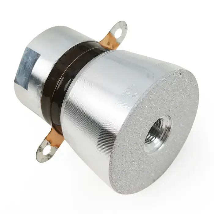
An ultrasonic 'transducer' looks like this:


This is the part that does the cleaning, and every ultrasonic cleaner has 1 or more of these. Think of it as a high-frequency tuning fork with an electric vibration device in it to keep it running. The two black rings in that photo are said electric vibrators (that work like speakers). They are a piece of ceramic that when you run electricity through them will expand/contract and send the frequency through the rest of the tuning fork. The length of that 'near to you' part is the actual tuning fork component.

My last attempt I chose the wrong vibrators (oscillators, etc). They didnt' want to vibrate at ~40khz, which is ultrasonic-cleaning frequency.

This attempt I chose ones I knew worked (since they came from something that looks exactly like below 馃榿). It managed to work!

BUUT, the frequency at which the tuning fork part (the horn, at the bottom) is currently at the length for, is about 4khz too low. My next step is to shorten it until it is a 'proper' 40khz tuning fork.

Thats about it 馃榾


As FURTHER progress: I messed with my circuit boards to generate the actual signal, and all 3 of them don't seem to come close to creating the right frequency, so I'm a bit confused/concerned why that is. i'd expect them to come close, but it is entirely possible I got scammed on aliexpress 馃榿

Going to get to debugging that, but will get my whole 'transducer can' done in the meantime as well, which includes shortening the 'horn', plus wiring/sealing up the case.
 
Posts
330
Likes
266
I have to re-figure out what the heck I was thinking 馃榾
Great thread. This made me laugh out loud, as I have often been there when returning to a deferred aspect of one project or another.
 
Posts
1,379
Likes
2,802
I'll try to do a better job explaining 馃榾

An ultrasonic 'transducer' looks like this:


This is the part that does the cleaning, and every ultrasonic cleaner has 1 or more of these. Think of it as a high-frequency tuning fork with an electric vibration device in it to keep it running. The two black rings in that photo are said electric vibrators (that work like speakers). They are a piece of ceramic that when you run electricity through them will expand/contract and send the frequency through the rest of the tuning fork. The length of that 'near to you' part is the actual tuning fork component.

My last attempt I chose the wrong vibrators (oscillators, etc). They didnt' want to vibrate at ~40khz, which is ultrasonic-cleaning frequency.

case.
Thanks, now i have a much better picture of it !
 
Posts
1,087
Likes
1,163
Took a minor rework(I left the center shaft too long, and it hit the little aluminum thing at the top!), but the head is back to assembled!

I still have to figure out electronics again (and think the driver board I have is overpowered/not right), but the machining is done!

I should have cleaned the lid before I assembled, but it is sealed up now, so nothing I can do 馃榿

 
Posts
1,087
Likes
1,163
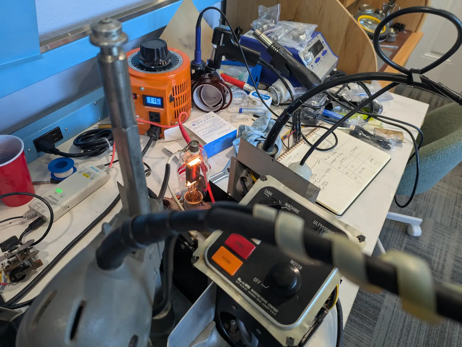
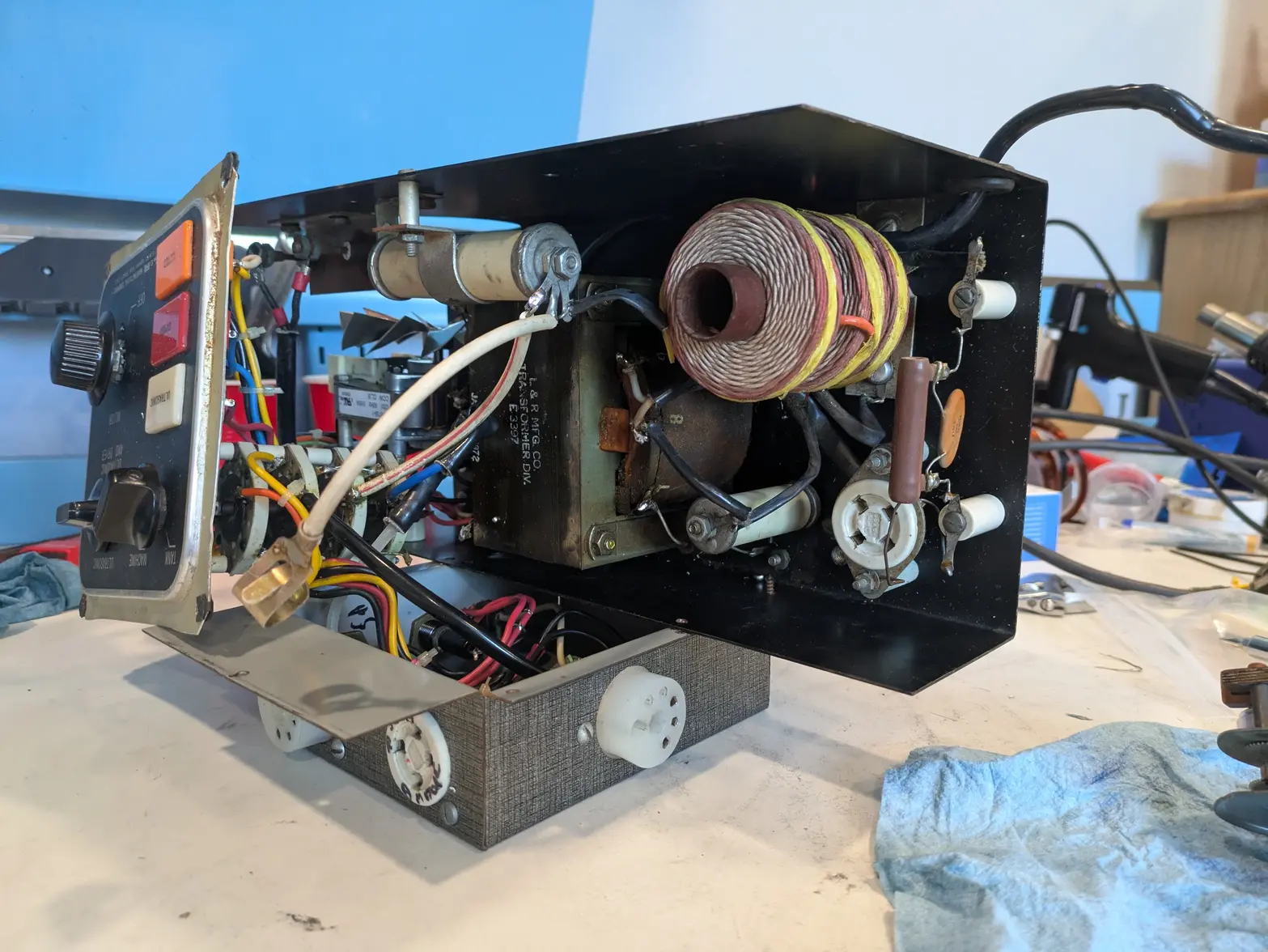
A little more effort today, I opted to spend some time investigating the electronics. Step 1 of course was to see if the existing (factory) ultrasonic generator part would work:

Here you can see the tube striking, so it is 'doing work' at least (it doesn't do that when not connected), but...


Sadly the answer is no. At best I got a weird 60hz signal. I could PROBABLY spend a few centuries trying to understand all of this, but it seems better to just replace it with something that I can buy.


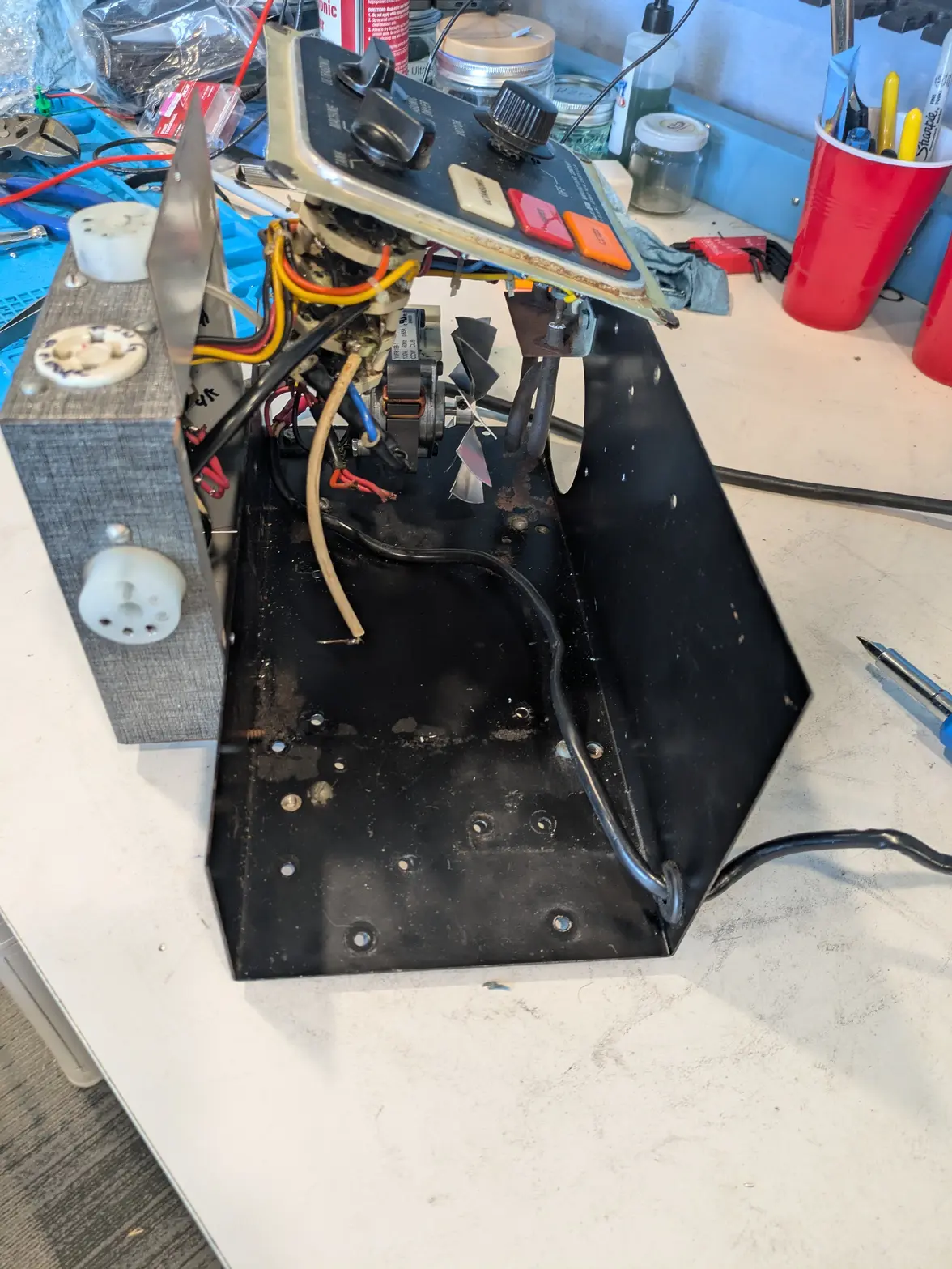
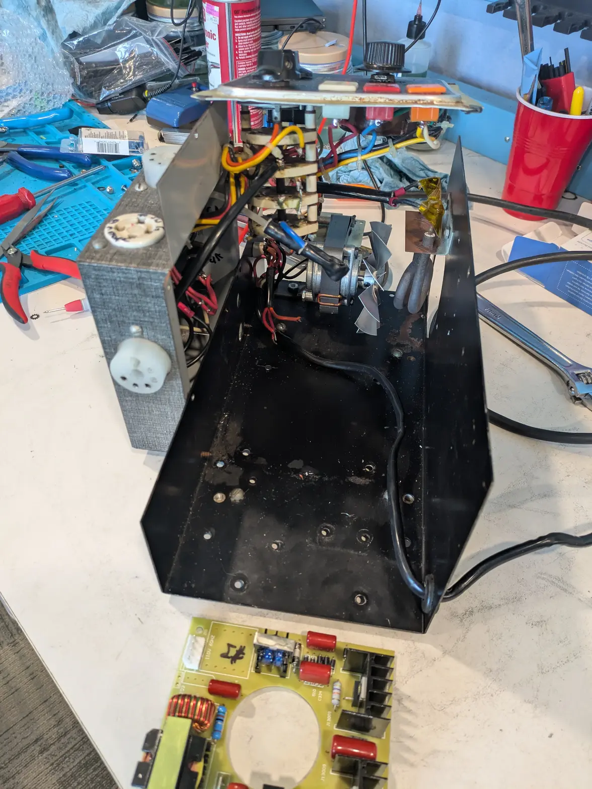
SO, I stripped the electronics out of the machine, which gets pretty small:

Those components strip out pretty easily, and leave a MUCH less weighty device 馃榿

The transformer itself is at least 6-7 lbs minimum. Half of the machine is empty it seems!


From here, I have some pretty minor wiring to do to power the board, then some minor wiring to get to the head wiring. I believe the 180W circuit board I have (not pictured!) is too powerful for my transducer and won't do a good job, so I have to order something different. Sadly, only available on Aliexpress, so multiple-weeks delay to receive.

I DO have a 60W board of questionable design/etc(pictured!) that I might give a shot to. It needs some sort of mount made, so I have to track down a piece of plastic that I can use for this. BUT that seems like a task for AFTER I've figured out which I am going to keep 馃榾
 
Posts
17,465
Likes
36,611
Amazing old electronic tech, all replaced now by something the size of a CD box (remember them?).

Just a point. My US cleaner specifies that the tank must be full when the transducers are on. I don't know if you need to immerse the head in water when test running or not to dissipate the energy away from the head.
 
Posts
1,087
Likes
1,163
Amazing old electronic tech, all replaced now by something the size of a CD box (remember them?).

Just a point. My US cleaner specifies that the tank must be full when the transducers are on. I don't know if you need to immerse the head in water when test running or not to dissipate the energy away from the head.
Right?

Yep, that is definitely the case. It isn't obvious in the picture, but I have the head in a full jar of water in this picture, so it won't oscillate. I also don't think the factory stuff will oscillate at the right frequency anyway (someone said it was 88khz, and I need something closer to 40khz ).

Either way, throwing a bunch of $20 off-the-shelf boards at this makes it much less problematic 馃榾
 
Posts
1,087
Likes
1,163
Another step back :/

I managed to get the wiring squared away I think. I still need to get the oscillator board screwed down, and probably get a different one in stock, but I got hte wiring squared away, and got the oscillator working.

HOWEVER, it wasn't outputting anything! I checked a few things and realized my transducer was a dead short. I pulled it apart to find water in it (I guess my water pump gasket maker didn't seal well enough SOMEWHERE and leaked. As a result, the two contacts (which I apparently let get too close together somehow!) were touching with some water. So OOOF.

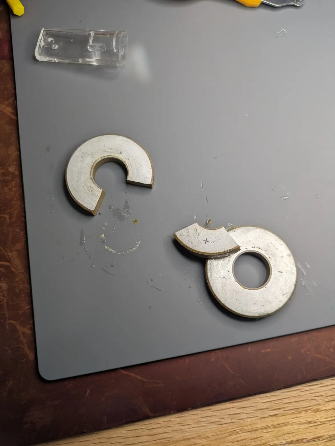
I went to remove the stack to find this: One of the ceramic piezos has broken. So, ooof. I think I have 1 more 'factory' transducer around I can disassemble to steal a replacement pair though.

I get the parts to finish up the machine side later today (mount the circuit board, but perhaps the wrong one!), the correct circuit board in 3 weeks...

I should get some shop time in the next few days so maybe I'll be able to get this working, but a big PITA to take a step back when I was sure I was almost done.

 
Posts
1,087
Likes
1,163
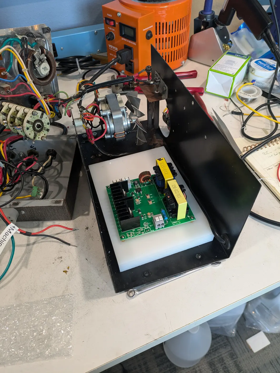
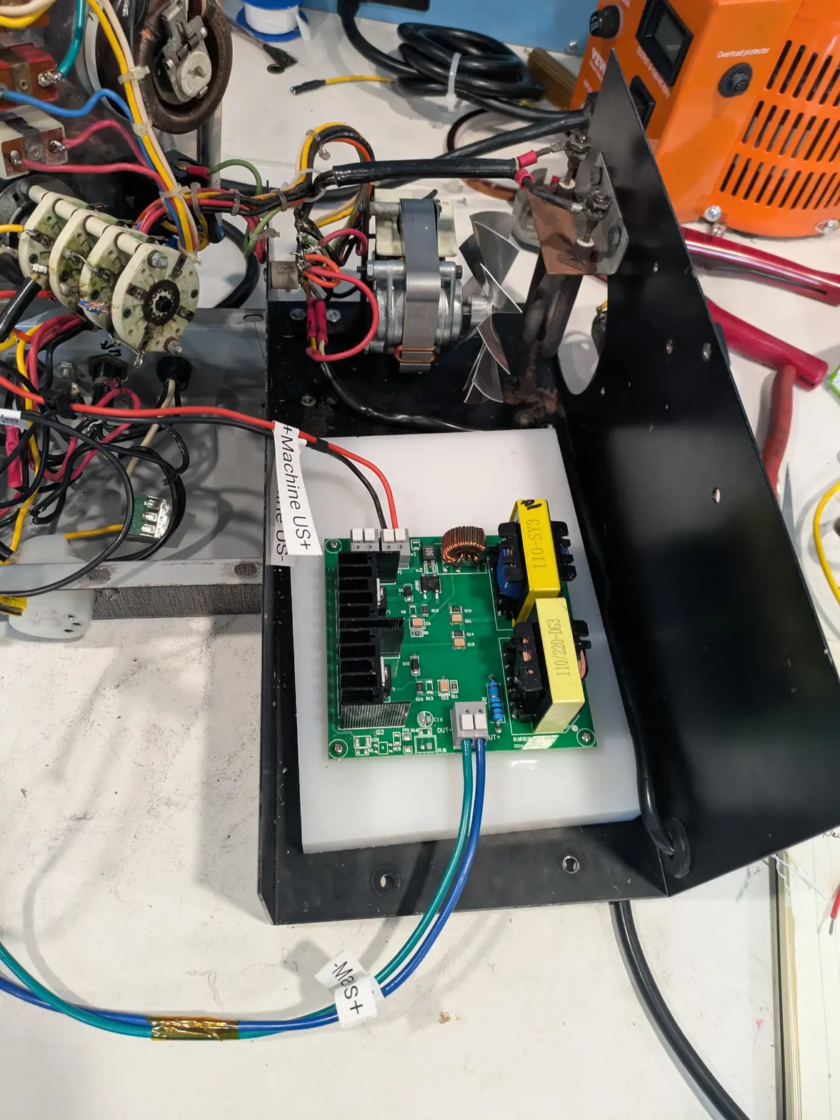
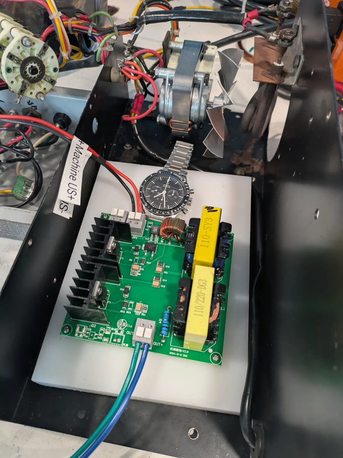
Had a few minutes between meetings/while thinking this morning, so decided to install the circuit board. I found a UHMW board of just the right size on Amazon that got next-day-delivered, so I just went with that. I did a .... rough job with my drilling unfortunately, so the board isn't straight, but I got the circuit board screwed down on standoffs easy enough. I made it in a way that I could use an off-the-shelf 2.5mm standoff setup, so if I ever decide to add a second board for the 'tank' side (almost definitely not going to happen for a few reasons), I can just toss some standoffs and mount the other board above this one.

This is still probably the wrong board, but the exact size/shape/etc as the right one.


Also, had a LITTLE bit of help, hopefully Ed wasn't looking too closely at the UHMW board install 馃榾