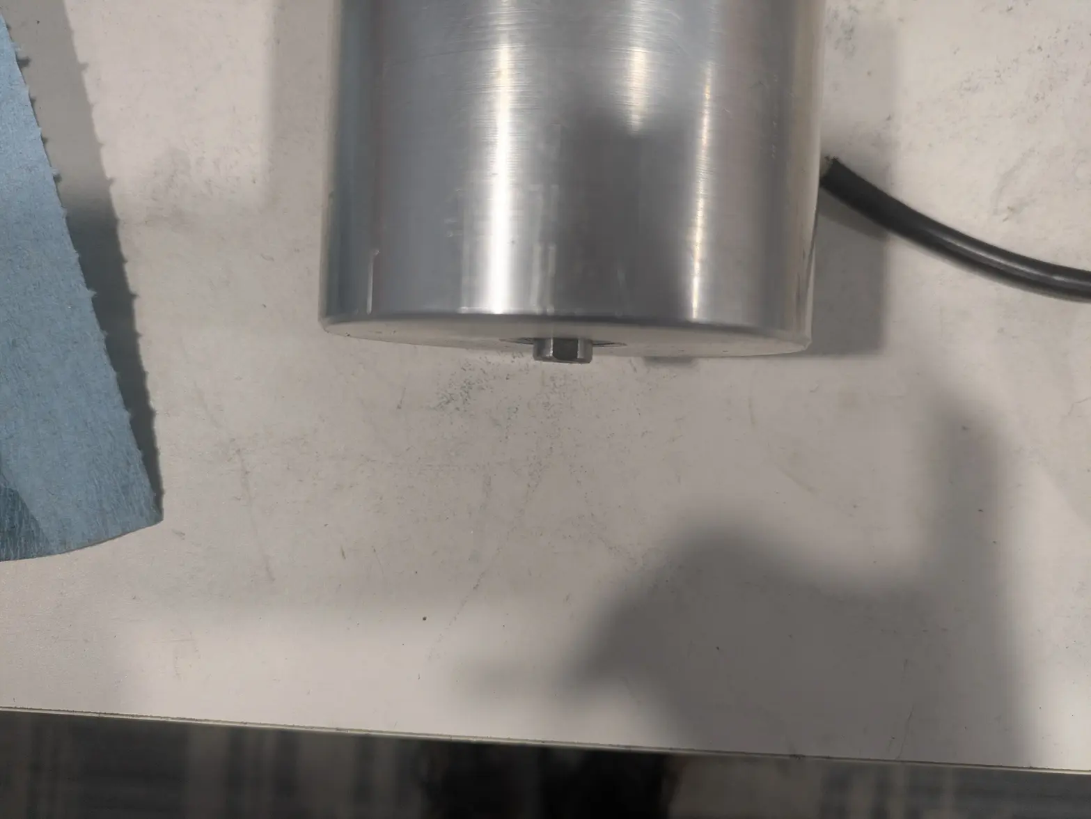
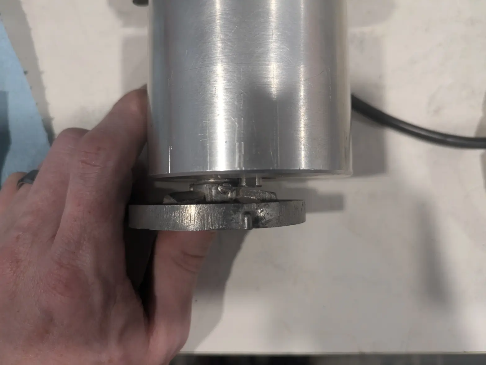
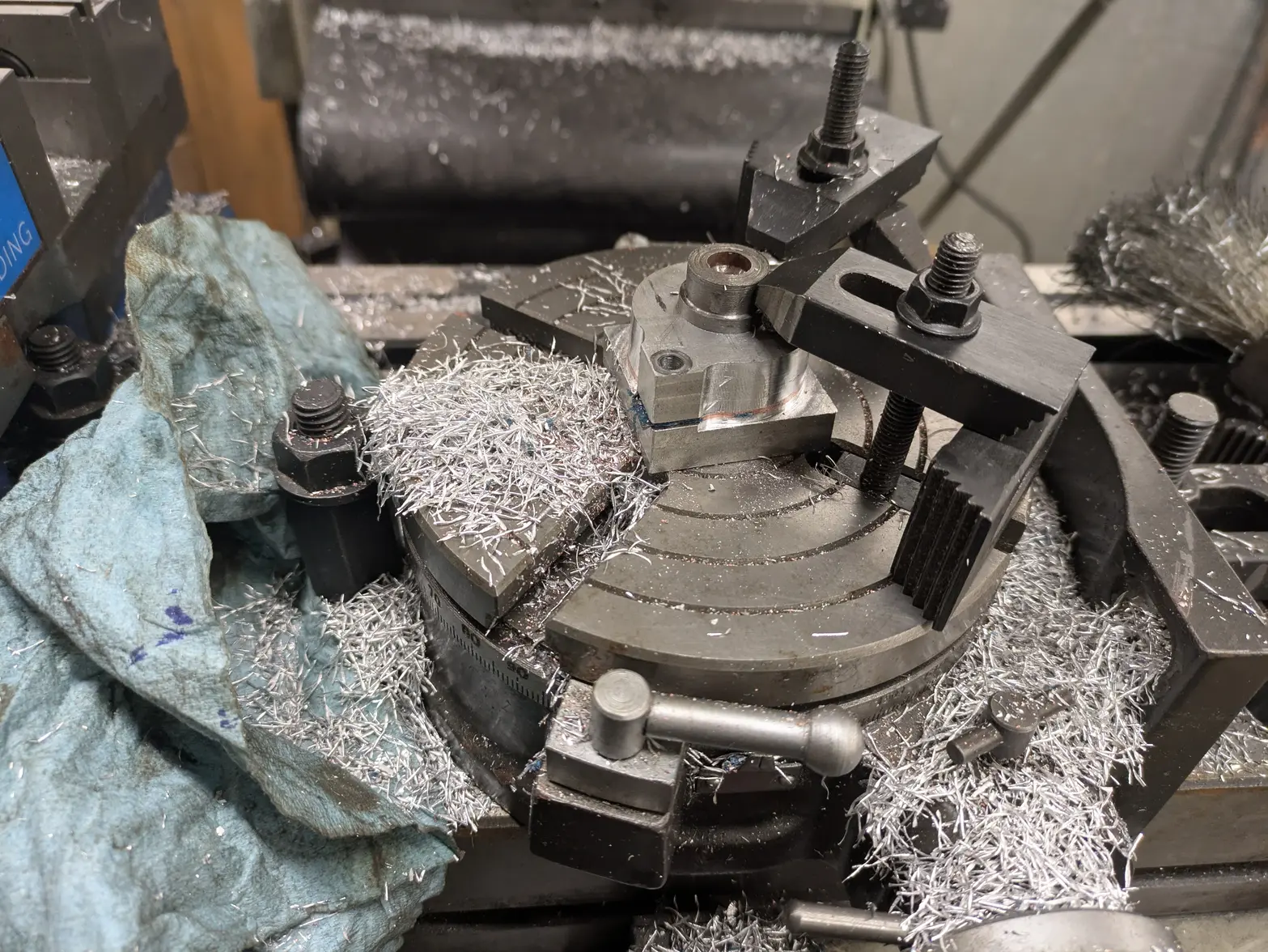
New(old)Tool day! L&R Console Watch Cleaning Machine

Posts
1,086
Likes
1,162
really enjoying this thread, keep it up. Amazed with what you are achieving so far.
Thanks! The next step is going to be REALLY hard 馃榾 I've been watching videos on designing a Transducer, as I can't seem to find one with the proper hole size. The nice part is I can possibly just do a bit of trial & error once I have the right piezo rings, which I might have a source of.

Its a little annoying how much has gone wrong, and now how much stuff I've ordered that I'm not not needing (like a vacuum tube!), but I believe I'm down to:

1- Motor side plug
2- Motor head stress-relief
3- Ultrasonic <everything>

to solve. #1 and #2 are reasonably easy, #3 is going to be a pain, but I'm workin on it!
 
Posts
1,086
Likes
1,162
So no real updates for a while so I figured I'd stop by and let you know what I am up to!

I reached out to a few folks, did quite a bit of research/etc, and have a 3rd grade understanding of ultrasonic transducers 馃榾 I also ordered some things to play with.

I needed to confirm practical implementation of transducers by doing 2 things:

First, I hooked up the transducer I have to the oscilloscope to figure out it's actual resonate frequency, plus figure out some additional frequencies. There is a "base" frequency, plus resonances at greater frequencies. Unfortunately the one I had first resonated about 40,080hz.

I then put it on the lathe, and shortened it about 1.5mm, and found that it raises the first frequency of resonance. I was hoping you could do "partial frequencies"(that is, that it was already on a not-the first, so I could make a smaller one resonate about 40k).

So in the end, I found out that shortening the transducer isn't possible, which unfortunately means it won't fit in the factory can.

Then I started to see if I could make a hole down the middle. It is glued together plus bolted (which provides a pre-load).

I machined out the base a little and got the below disassembly.

What I found was reassuring! The ID of the piezo rings is 15mm, and it is insulated! Which means making the 10mm motor shaft go through it is perhaps possible.

I believe now that if I make my own can, with a steel center shaft that acts as a bolt, plus the little extra room in the machine, I should be able to just disassemble one of these (I have another on the way!), remove the bolt, then put it in a new can.

From there it is just wiring, which I know how to do.

Sorry for the few pictures, the last few days were mostly researching it! And today was attempts at disassembly and experiments!

 
Posts
1,086
Likes
1,162
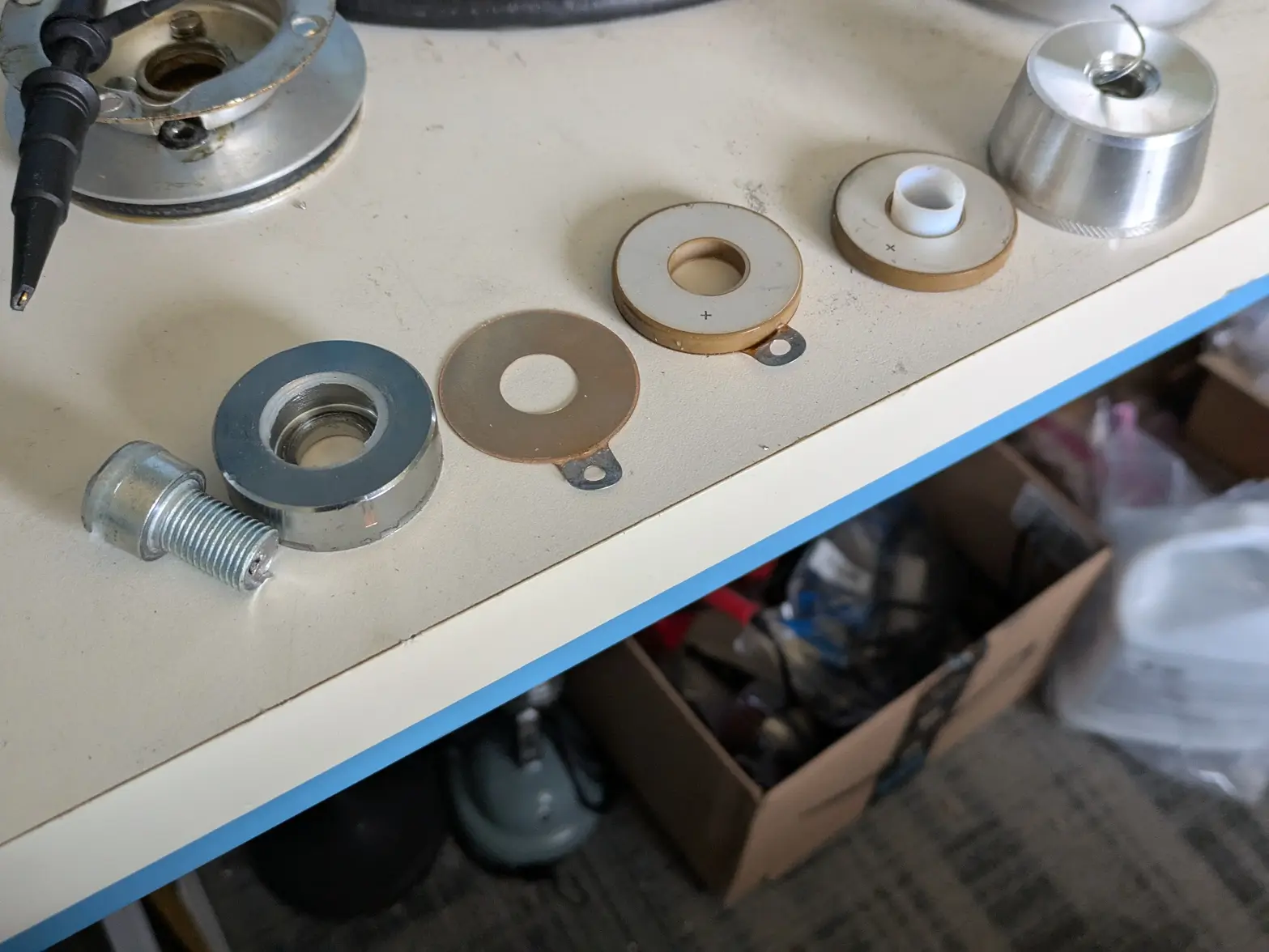
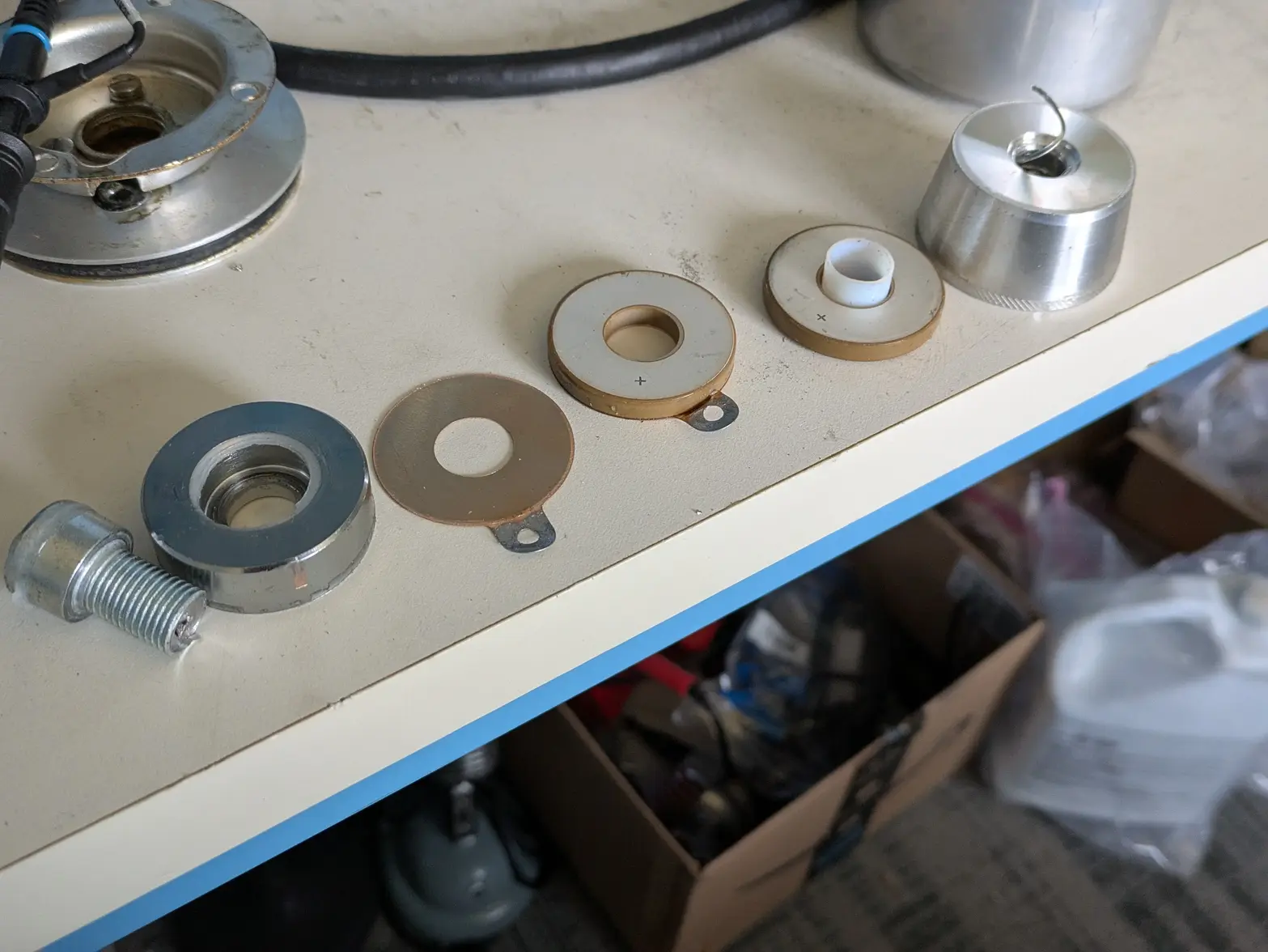
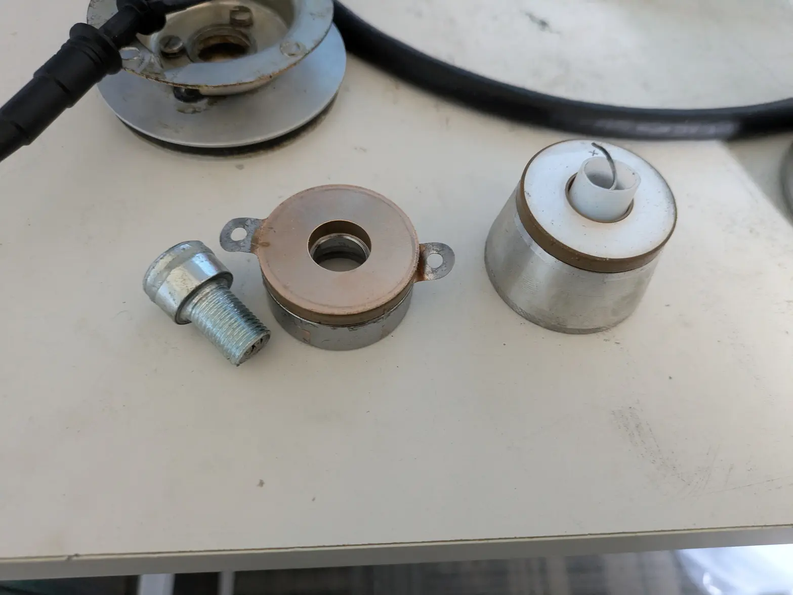
Alright, to explain what I'm doing, I have to explain the parts of a transducer based on that above picture.

FIRST, all the way on the right, is the 'horn'. This is the most difficult part of the whole thing, since its 'height' is what sets the resonant frequency. The shorter this is, the 'higher' the frequency that the transducer has to run at. The resonant frequency of this will cause the ultrasonic cleaning effect of cavitation/etc.

Next on the right is the piezo rings. These are effectively ceramic speakers, where you put an electrical signal into them, and they expand/contract.

The rings with the little tabs (connected to the left-most piezo ring, and individual next to it) are the conductors where you attach the signal wires. The two 'plus' sides face the middle and touch eachother, and the negatives 'face out'. On a normal off-the-shelf transducer, they use a 2nd conductor ring to make wiring easier, though it isn't necessary, as the idea is that BOTH aluminum pieces are electrically attached, so they are both the 'signal ground'.

The last part is the cap (all the way on the left) and the screw. The cap's purpose is to be a bit of a 'counter weight' to the whole mechanism, plus distributes the clamping force of the screw. The screw holds the whole thing together, PLUS adds enough 'force' on the ceramic piezo rings to keep them 'preloaded' so they don't try to disassemble themselves.

Today I spent some time on my lathe trying to make the first piece of this arrangement, and hit the point where I can no longer do any further work until tools show up on Monday! Next post will be progress on that.
 
Posts
1,086
Likes
1,162
So the first part I started on, and kind of the key to this whole device, is a horn that also includes the 'cup' from the machine, and has a hole down the middle for the purposes of letting the motor shaft through it. The motor shaft is 10mm, but the clamping force needs to be quite a bit.

I also have 2 sizes of piezo rings. First are the ones harvested above, which are 38mm OD, 15mm ID. Second are coming in a week or so, and are 40mm OD, 20mm ID. I believe the latter will be more 'powerful' and have the bigger inner circle. Because of this, I want to make sure this horn will work for both.

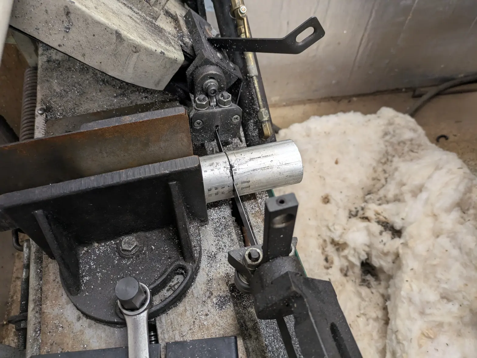
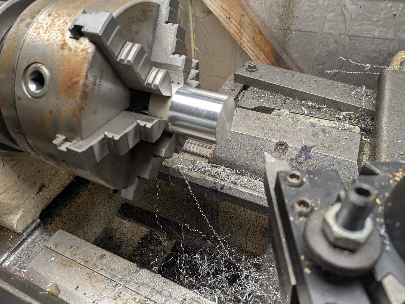
ONE thing that WILL happen with this, the transducer on this will be smaller than the factory can, since that is 3", and I don't need anything bigger than 2". I started with some 2" aluminum bar stock, and cut to a little more than 3" long.


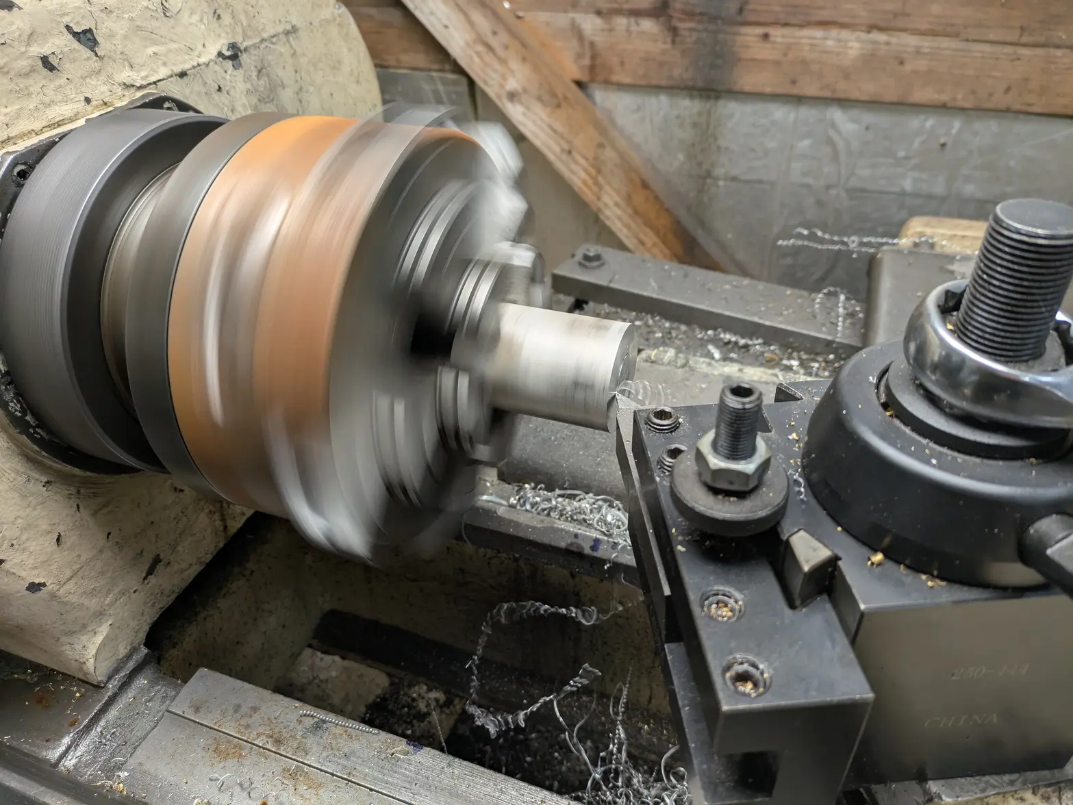
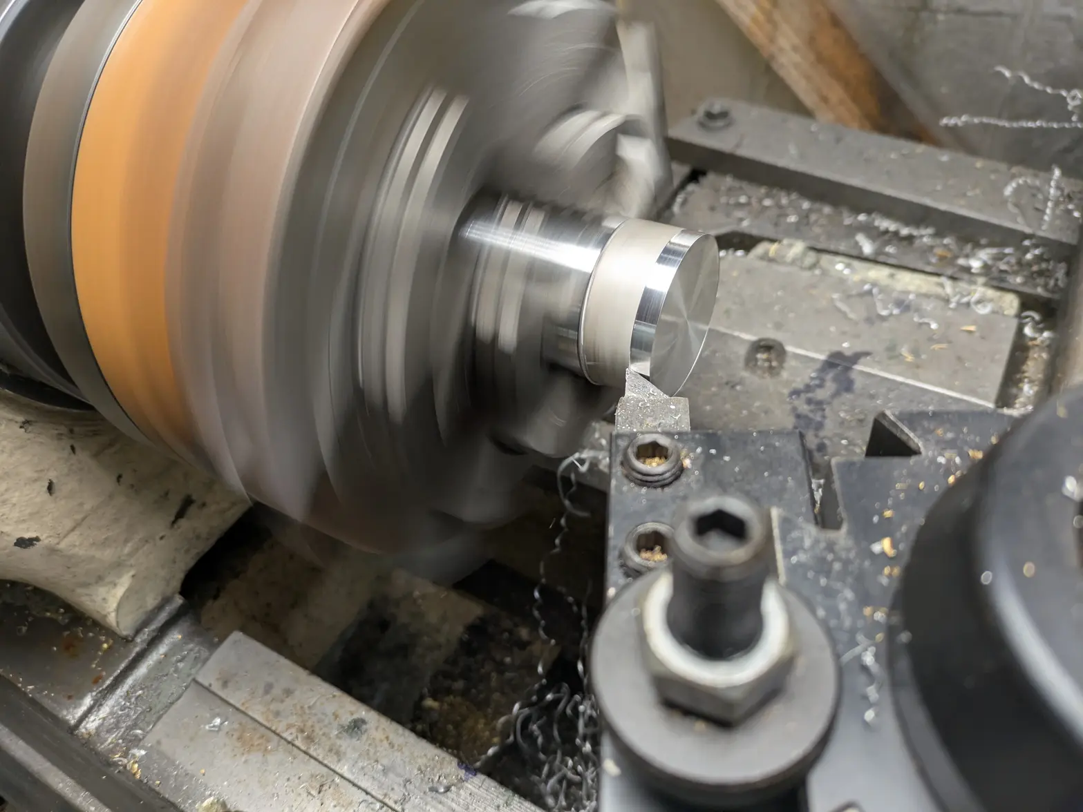
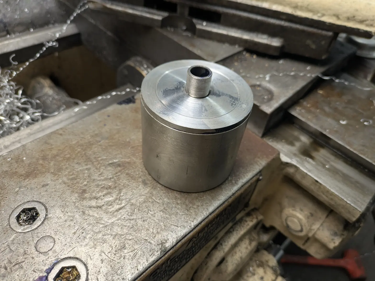
Next I faced and turned 1 side. Facing it makes the 1 end flat/square, and I decided to do a bit of outside turning to make it 'nicer' than factory drawing marks.


After:


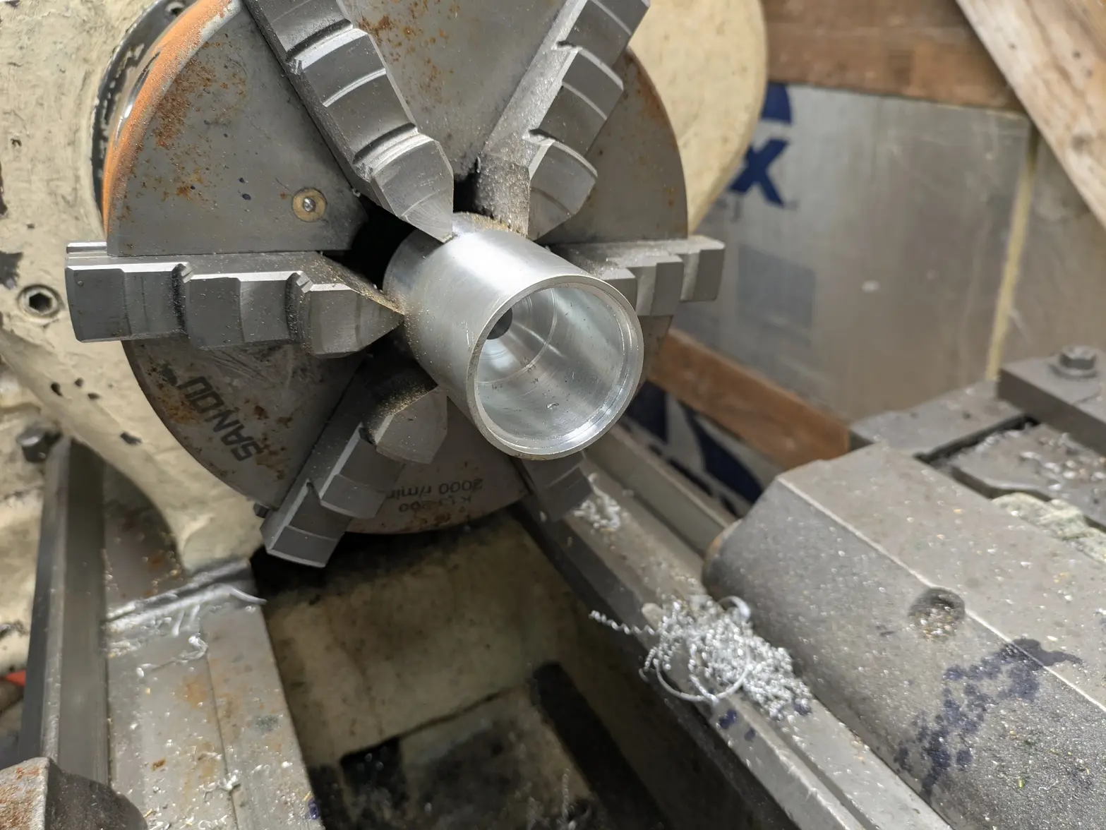
Next I flipped it around in the lathe to do the other side, and faced/turned it. A 'better' machinist would have spent the time to dial it in, as the two won't end up being consentric, but I don't think it matters as I'll do all the work from the other side so that they happen in the same setup. So the only thing that will be 'wrong' is a line between the outside diameter turning from each side:


I missed a photo, but I drilled the center hole to give clearance. I'll eventually be threading this 3/4"-16, which will allow me to make a hollow shaft down the center to be my 'clamping' bolt.

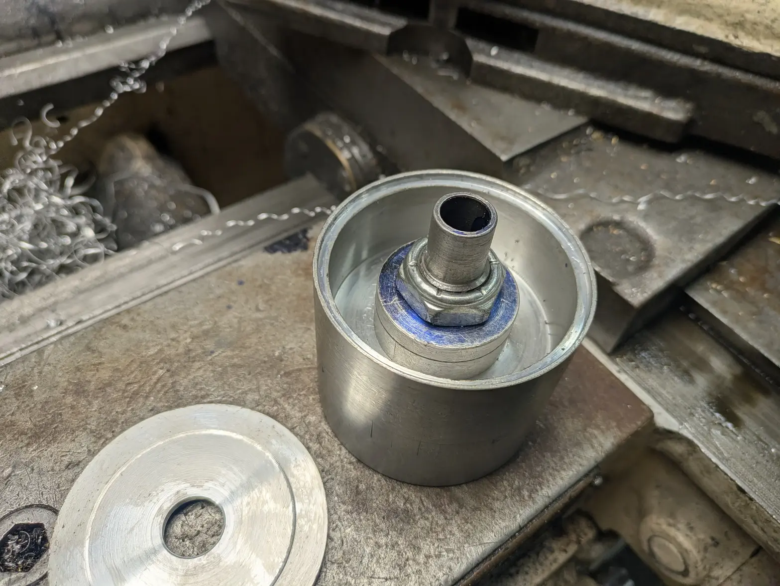
I also started making the clearance for the 'rest' of the transducer parts, plus a nut. I basically just turned the center out.


Here is how it turned out after 1 night.


You can see at the near side that I made some room for the 'cap', which I'll use something to seal off to make this whole unit water tight. Next you can see the clearance, where both piezo rings, wires, and the cap + bolt-head will go.

Finally, you can see the through-hole.

My next steps are: I want to cut a 'bevel' on the inside of it so that it is more 'horn' shaped like the previous one. I want this one to be effectively a 'horn in a cup' design, but as 1 piece.

Also, I have to increase the size of the center hole for 3/4"-16 and tap it (thread it).

There is 2 more parts (the 'hollow shaft + nut') that I'll have to make for this before I can start testing it. I left the bottom of the horn quite long (about 30mm, the factory one is ~25mm). The idea is I can test the resonant frequency on my oscilloscope (let me know if anyone is interested how to do that!), then remove material until I get to exactly 40khz (or at least, close enough I can adjust my driver to do so).

ONCE I have that dialed in, I expect this will be JUST short enough to still fit on the motor shaft and allow the basket holder to still work, plus wiring/etc. I'll still have to make the cap + assemble it in some manner, but those are all details for future Erich 馃榾

As I said, I won't have the ability to make any more progress for a few days, but if anyone has questions, feel free to ask!
 
Posts
17,464
Likes
36,610
I don't know why you bothered buying that old junker.

I think you could have built one from scratch yourself.

馃槈
 
Posts
1,086
Likes
1,162
I don't know why you bothered buying that old junker.

I think you could have built one from scratch yourself.

馃槈
I considered building something actually, there are plans for a 3D printed one that looks really cool, but I would have to figure out how to modify it for an ultrasonic. I thought I could perhaps make some of the plastic parts on that out of aluminum to make it more skookum.

I bought this figuring it would be LESS work 馃榾 Though, we see how that turned out!

Side note: there is a Varimatic 3 about 90 minute drive from me on facebook marketplace that I'm resisting buying. I'm sure it too would be a basket case, but at least I know all the details now! That said, I'm hoping to be 'done' with this soon enough I can go back to spending my time on watches, not the cleaner!
 
Posts
1,086
Likes
1,162
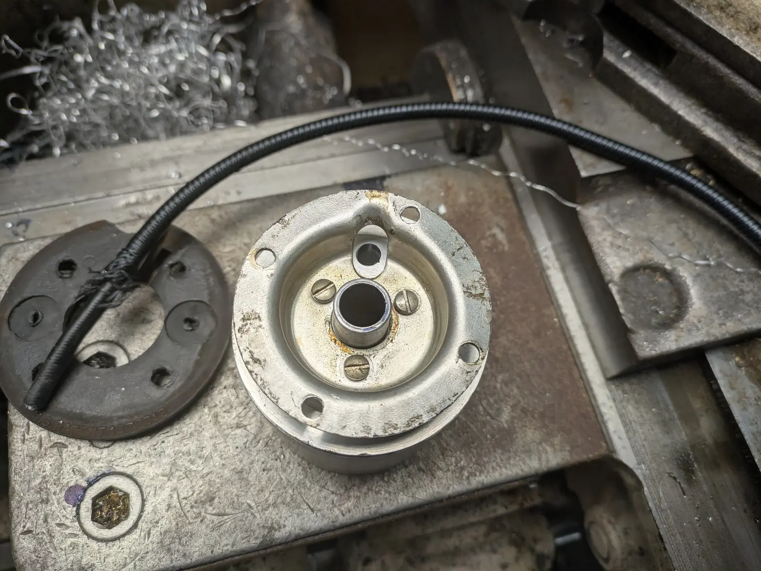
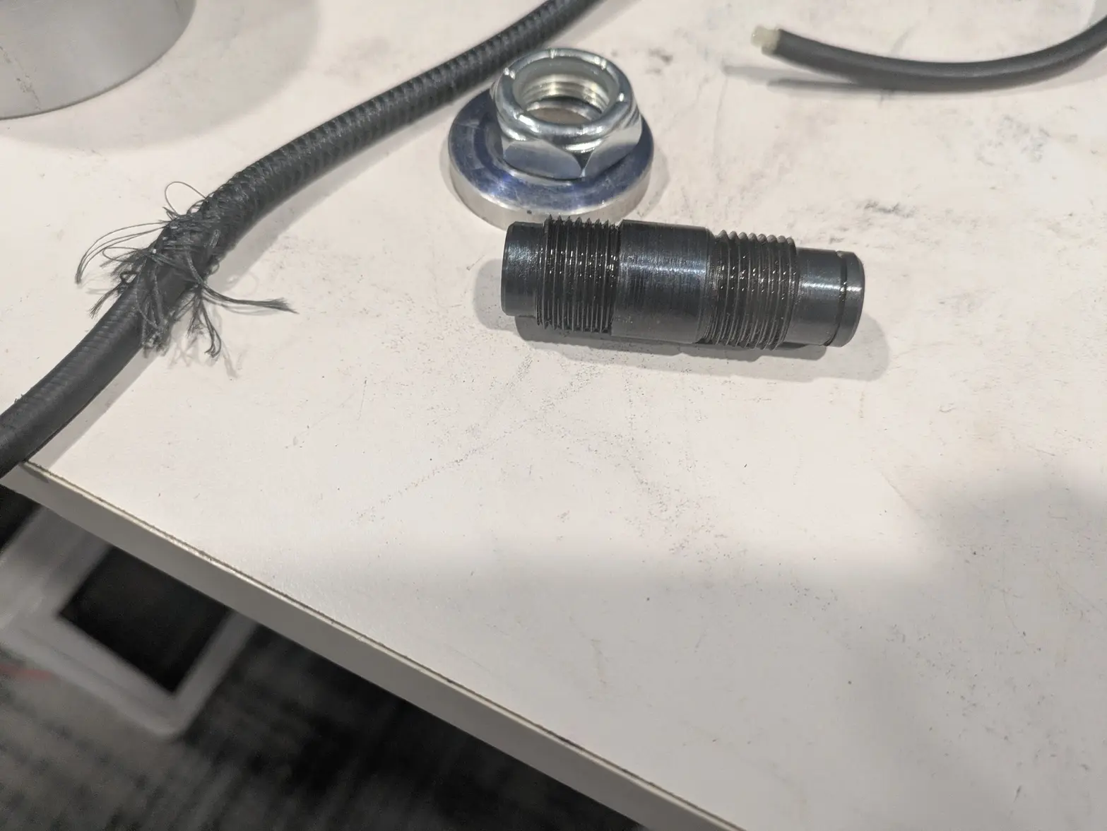
I am still waiting on some tooling to work on the 'horn' more, but I spent some time on the motor cable today. I didn't get any good pictures of the head-side, but it turned out... fine. I used some 3/8" fuel hose slit down the side and some heat-shrink tubing to make a strain relief.

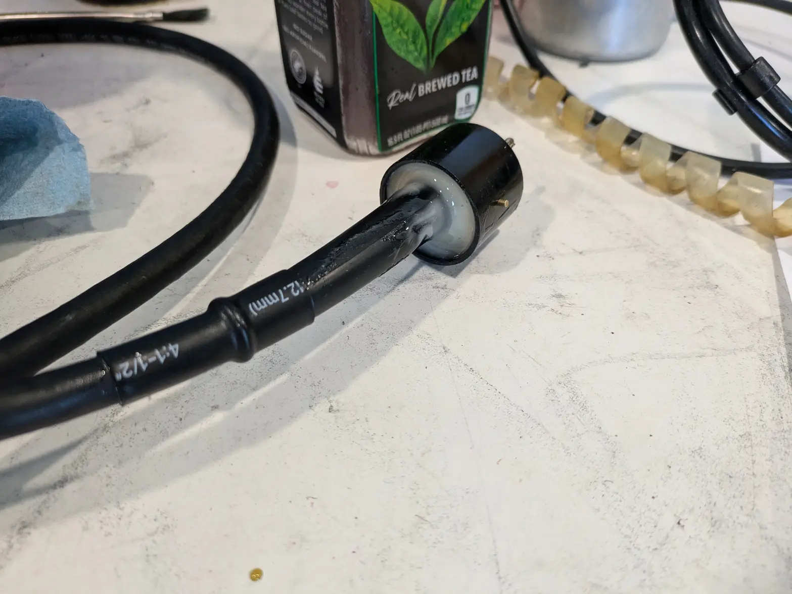
On the machine side, I finally got my tube sockets in, so did that soldering and did some epoxy + heat shrink + a off-the-shelf 'boot'. It looks like it'll work out great 馃榾

I have some tasks for my transducer 'horn' when some tools show up, then a couple more parts to make it functional, so probably a little bit more time before I can figure out if I'm doing it right.

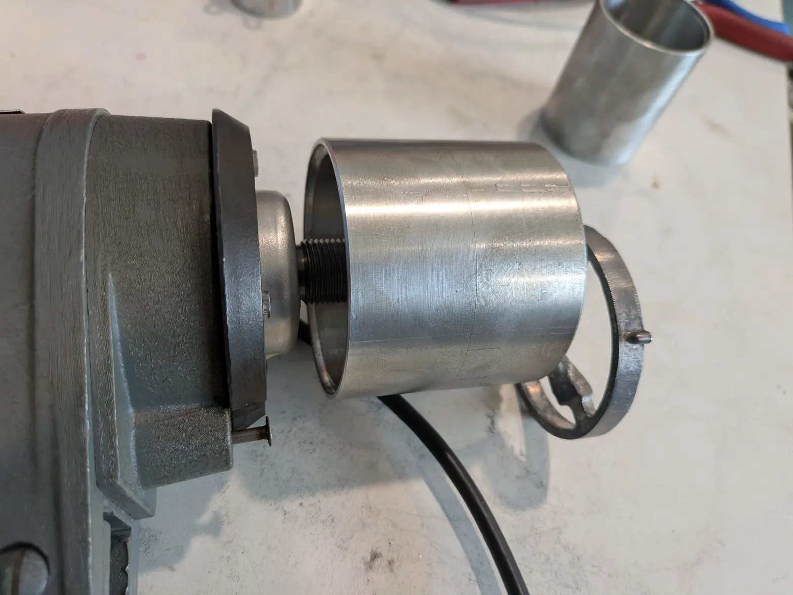
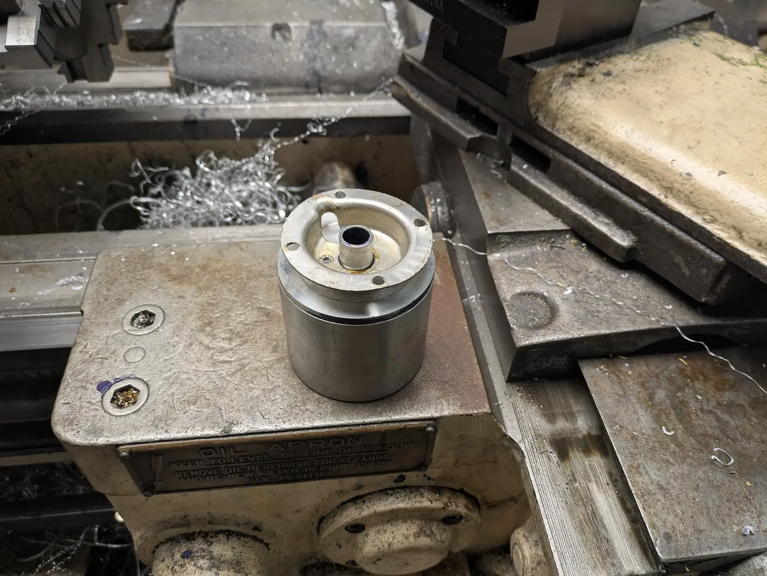
I DID do a bit of a mock-up with the head. If I choose to use the factory 'bracket' (a stamped metal plate that connects the head to the cap of the old transducer), I have ~2.35" of room before the basket 'holder'.

Currently, my transducer horn is ~2.9", so I have some depth I need to get back.

First, I know already I'll lose ~5mm off the bottom when tuning for frequency.

Second, I gave myself a LARGE distance for the clamping nut (~.5") I suspect I can go with a shorter one for that.

Third, This is based on the normal aluminum 'clamping cap', which is 13mm thick. It has a depression for the clamping nut that I didn't include in my depth calculation. So I can re-make that differently, or customize the nut if necessary.

Next, I can pick up a little more room if I either modify the factory bracket to allow more clearance near the middle, OR I can make the 'bracket' integrated in the cap. Its more work, but probably saves me some space.

Finally, and only if necessary, the basket clamp has some additional space I can steal. I can machine off a few millimeters if necessary to get myself a tight, but complete fit.

SO, I'm still somewhat confident that I can get this to work!

 
Posts
1,086
Likes
1,162
WELP, Today was a 1 step forward, 2 steps back kinda day! I'd mentioned before, I was hoping to use the piezos from a transducer that I took apart, which are 15mm x 38mm x 5mm. The nice part with them, is they come with the contact plates, the tensioning cap pre-made (though in need of modification), and I can measure against an existing one for pre-load/etc.

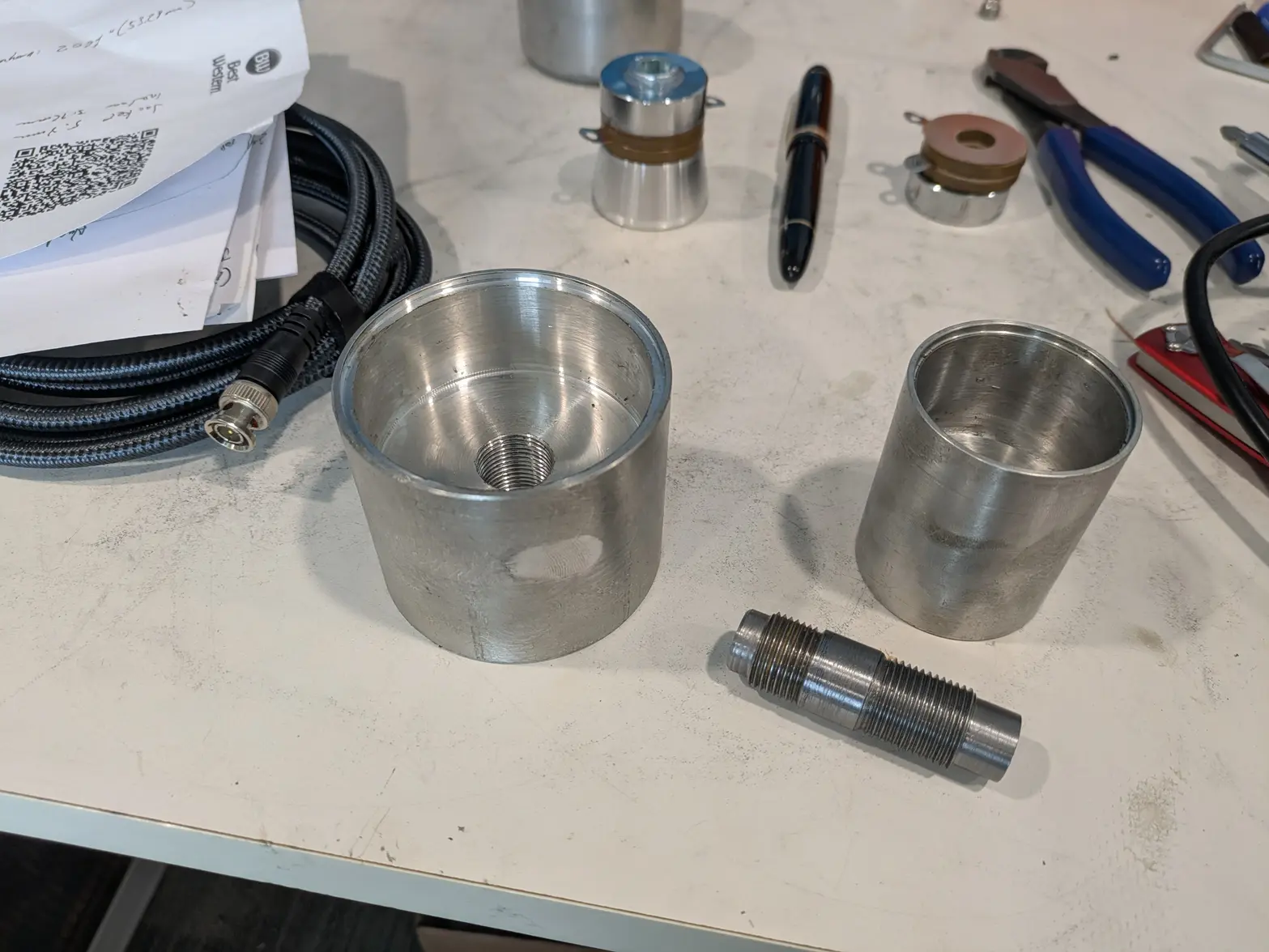
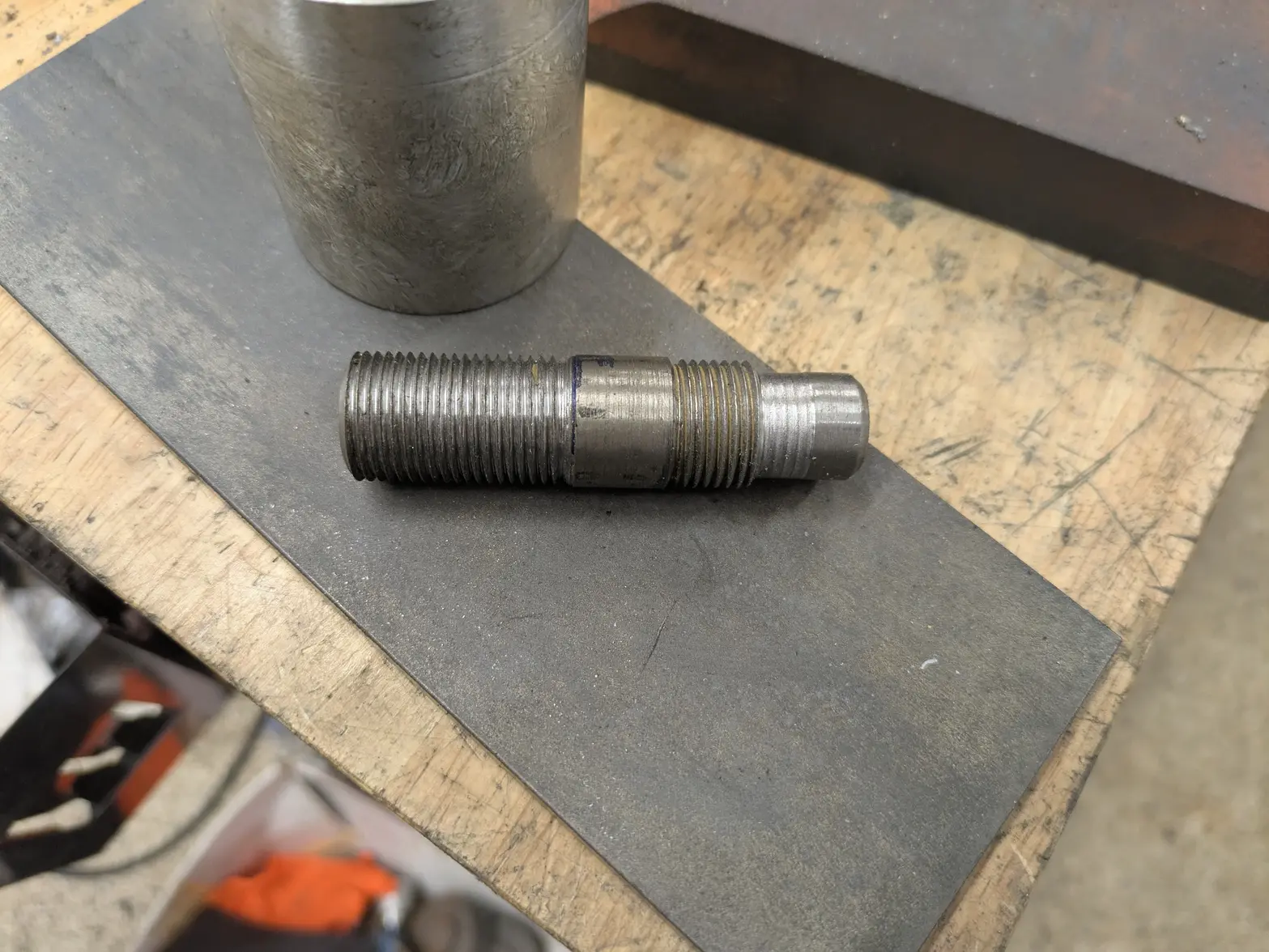
As I'd finished up the horn, I started on the 'center shaft', which is a fairly critical part. It is the clamping bolt, but also has the hole in it for the spindle. It needs to let a ~10mm shaft through it (factory 'hole' is 1/2", so I chose a little less than 12mm), but also clamp everything down. I'd decided to do a 9/16-18" thread on the top of the shaft (but 3/4-16 on the bottom, both to improve the clamping in the aluminum, but also because I didn't want to have to re-make the horn/cup in case the smaller size didn't work).

I had the shaft made, plus the horn, so I went to assemble the whole thing to get a proof-of-concept working (with some place-holder piezo-like blocks)! Unfortunately as I was torquing down the nut, the shaft snapped. The amount of metal between the root of a 9/16-18 and a ~15/32" center-hole wasn't enough to hold really any torque whatsoever, and pulled apart.

SO, I was forced to make a new center shaft, this time throwing out any ability to use the 15mm bore piezos. I DO have some 20mmx40mmx5mm ones on order, which allows me to use 3/4-16" threads! AND because I made the horn with the design I did, I can just re-use the existing horn.

I made it, and it looks great! The wall thickness of the shaft looks like it should be sufficient, more than 0.100" of wall on each side.

UNFORTUNATELY, I went to put it into the horn to find out the hole tapped in the horn is not straight. Trying to clamp this down on the piezos would crack them.

SO, I have to start making a new horn. I did some roughing-out work today (and quit when a bunch of stuff started going bad!) out of some 3" stock this time (previously I used 2-3/8", but turned down to 2"), which lets me do a better job of making this look like the 'factory' one in dimensions, since it too is 3". This was something I'd already regretted, since I want to make sure I have enough room to add the wiring correctly after the fact as well. BUT, I was hoping to save it for V2 :/

In the end, I'm further behind tonight than I was last night, and now have extra tasks (having to make the contact sheet in particular!). AND I have to wait quite a bit of time for the bigger piezos, so this won't get done this week/weekend. Likely not next week/weekend either thanks to company.

Pretty disappointing, I was really looking forward to 'tuning' it in tomorrow :/

 
Posts
1,086
Likes
1,162
Got a little more time in the shop and made the shaft and new cup/horn, both of which turned out better. I've got a few more parts to make before I can even assemble it to tune it, but am getting there! The whole assembly is more than 1/2" too long at the moment, but I have a few places I can save some space, but that is likely going to be as a part of the final tweaking.

In general, I'm happier with the design of this one vs the old, I made better decisions in a few places that would probably have bothered me.

Piezos don't show up until mid next week though. So I have time 馃榾

 
Posts
1,086
Likes
1,162
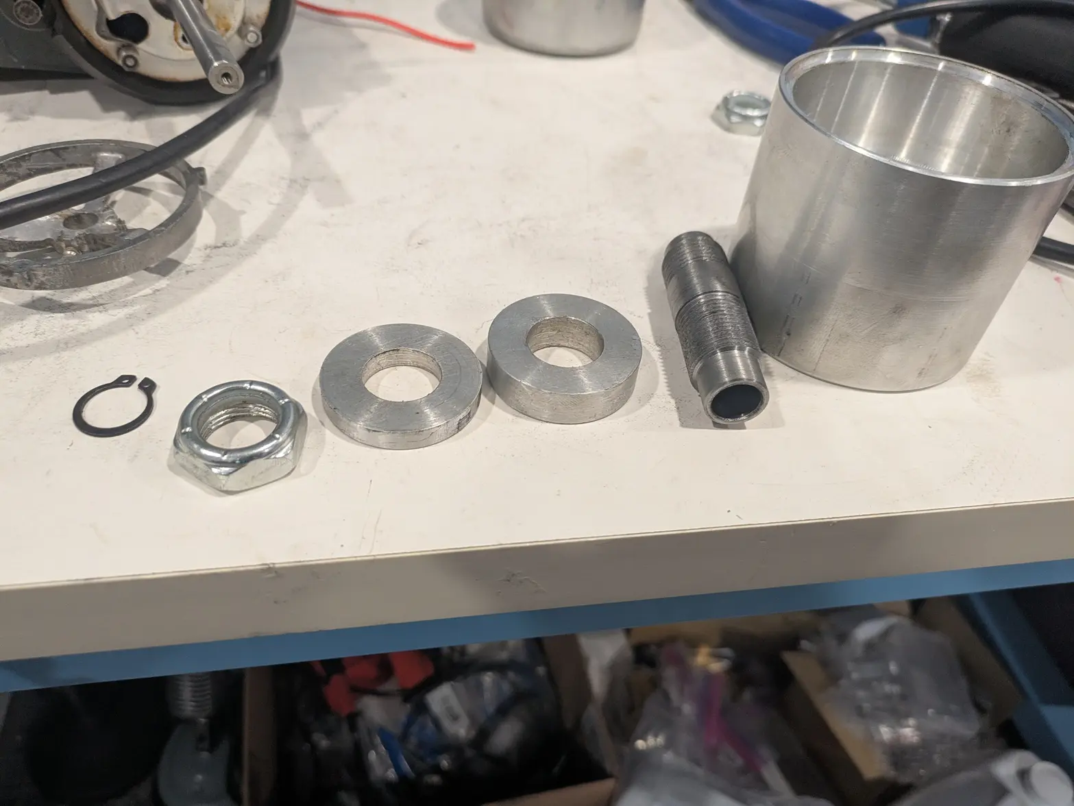
Another steps-forward/steps-back kinda night. I made quite a few parts last night, plus got in some snap rings and 3/4-16" nuts.

I made the clamping plate, which goes under the nut to distribute the force on the piezos. I also made a 'mockup spacer', which is taking the place of the piezos/plates while I work. I also made some jigs that'll help me cut the copper plates.

Here is the whole assembly:
Snap ring, hut, clamping plate, mocked up piezos, center shaft, horn:


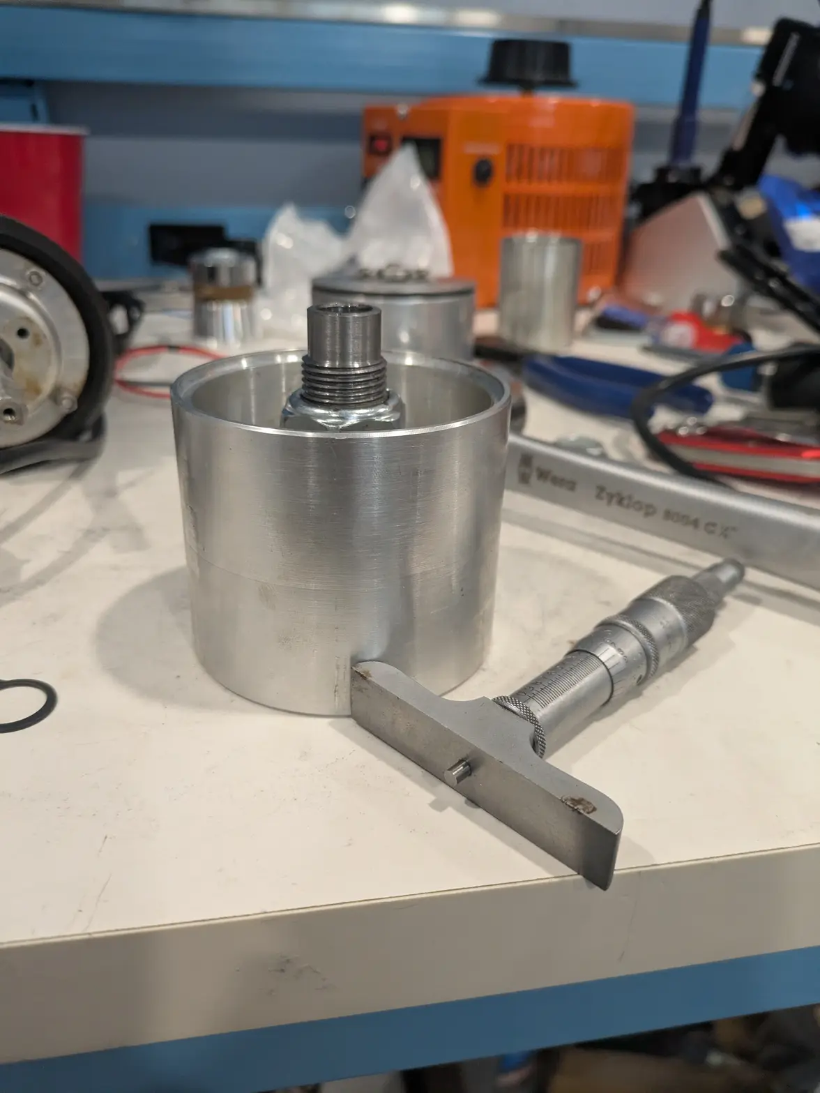
Then I assembled it:


At this point I had some tough times measuring how much space I had. I did a bit of envelope math/etc, and decided that I was ~93 thousandths 'tall'. SO I went to the lathe and took that much off, then did a test assembly. TURNS OUT I wasn't 93 thousandths 'tall', I was 7 thou "short". SO now I am more than 100 thou short, which is frustrating.

I now either have to remake the cup/horn part (AGAIN, 3rd time is the charm?), or come up with some way around it.

SO remaining tasks:
1- Fix/rework/remake the 'cup'
2- Make the copper 'contact' plates
3- Make the 'cap' (top)
4- Cut down the center shaft to length, and cut a snap-ring groove in it (in the right place!).

After those 4, I should have a near-fully assembled transducer of unknown frequency. At that point:
5- Experimentally trim down the transducer until I can get within spitting distance of 40khz.
6- Wire up the copper plates to the BNC cable, and through the cap
7- Use an epoxy to keep the BNC cable in place in the cap.
8- RTV (or something?) to seal the cap, and assemble everything.

At that point, I should have a fully functioning transducer I can put on the head, and be done 馃榾 A few unknowns left (#1 and #5 in particular!), but most I've been thinking about for a while. ALSO still waiting on the copper plates and piezos to show up still.

THEN, after all that is done, figure out the wiring again and change the console itself over to the new driver 馃榾
 
Posts
1,086
Likes
1,162
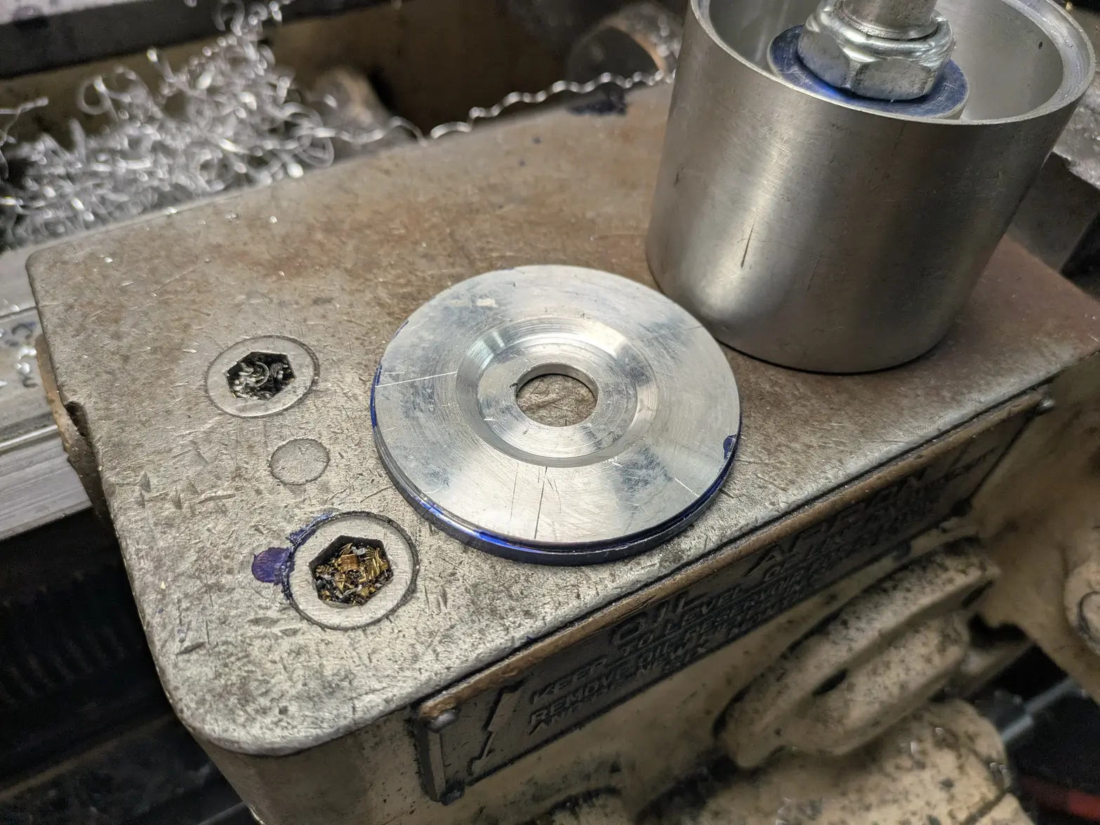
Actual progress made last night! Instead of remaking the horn, I changed the design of the cap to be thicker and have a depreasion for the nut.

I still have to drill/tap the holes for the stamped bracket, plus the hole for the wire in the cap, and cut a snapring groove in the center shaft, but I am pretty close to having the "top end" machining done!

I also got copper sheets in the mail so I can make some contact plates, so hopefully when the piezos show up Tuesday I will be all set/ready to go on getting the frequency right!

 
Posts
17,464
Likes
36,610
Starting to look like it was factory made Erich.
Question: Is the transducer housing partially immersed in fluid when operating? Or is the ultrasonic effect transmitted through the basket holder?
 
Posts
17,464
Likes
36,610
PS: Looking at it now, that was a silly question. The basket holder is on a free spindle through the centre of the transducer so would impart no US and the transducer would need to be in contact with the fluid to achieve cavitation.

Those jars must be tall buggers!
 
Posts
1,086
Likes
1,162
Yep, you got it 馃榾 about 1/2 of the transducer is submerged I think, so the basket is completely under, and the end is submerged.

At one point I'd like to look into making it NOT needing to be submerged to not damage the driver, but that requires better circuit design than I have 馃榾
PS: Looking at it now, that was a silly question. The basket holder is on a free spindle through the centre of the transducer so would impart no US and the transducer would need to be in contact with the fluid to achieve cavitation.

Those jars must be tall buggers
 
Posts
1,086
Likes
1,162
Finally an evening that went to plan 馃榾 Not a particularly long evening, and I got everything to go as planned.

FIRST thing I did was some trig 馃榾 I had to figure out the dimensions of the 3 hole pattern, which took me longer than it should have!

THEN, I set it up in the mill with the bolt circle tool to drill and tap those 6-32. I then measured and 'free-eyed' the wire hole to be bigger than the wire I'm going to use in a reasonable location. I assembled everything at this point, and marked the center shaft for the snap ring.


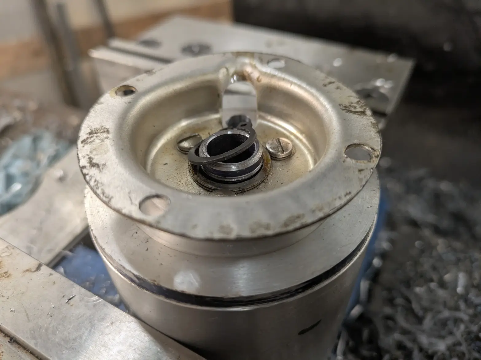
The center shaft went back on the lathe for hopefully the last time, I shortened it a ton (after this photo!), plus put the snap ring in a place where it'll be a little 'loose' to make up for the RTV gasket that is going to hold this together.


Here is a good look of how it'll fit, right before I put the snap ring on. You can see I left a tiny amount so that the gasket-material can have some room.


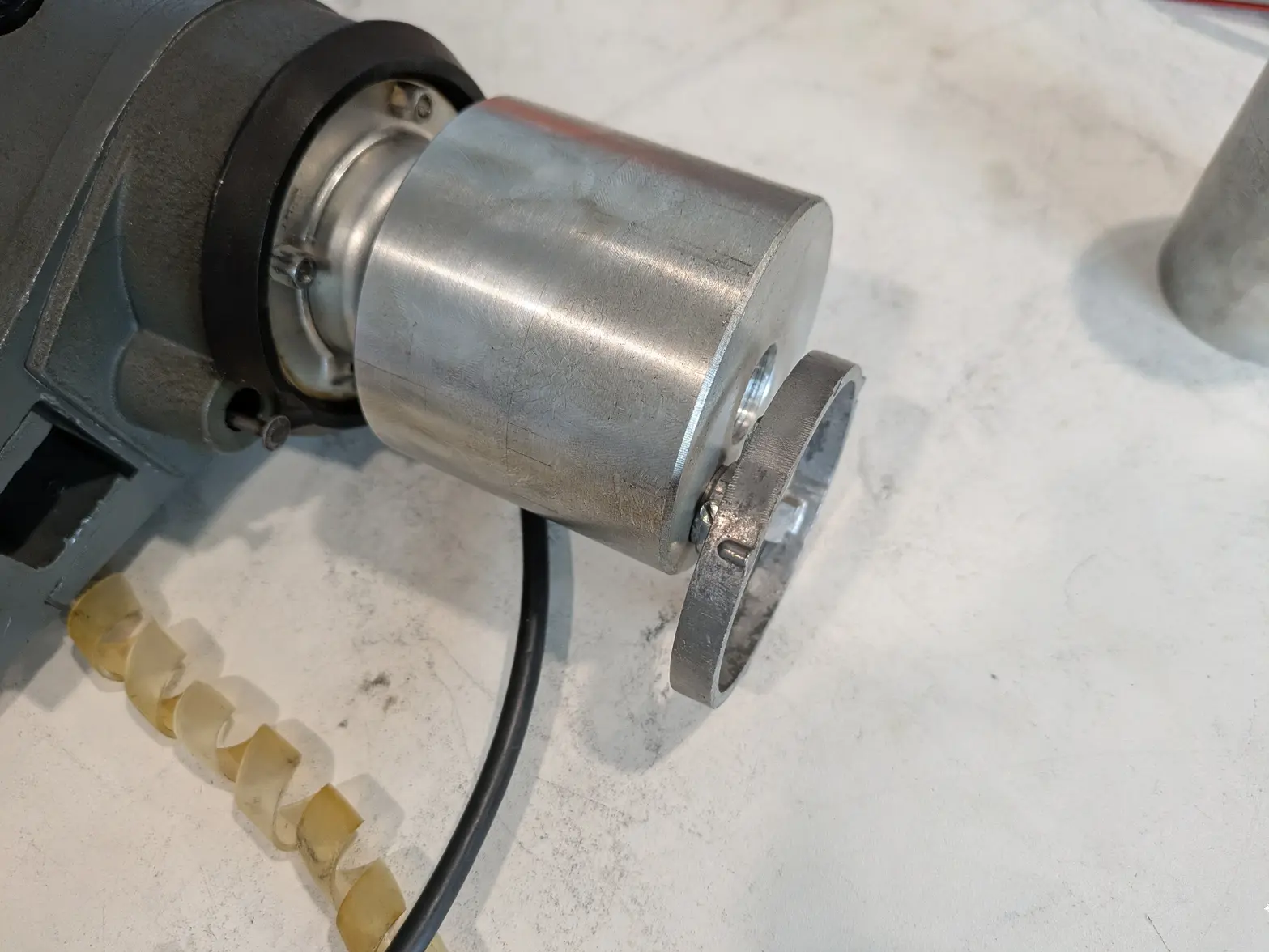
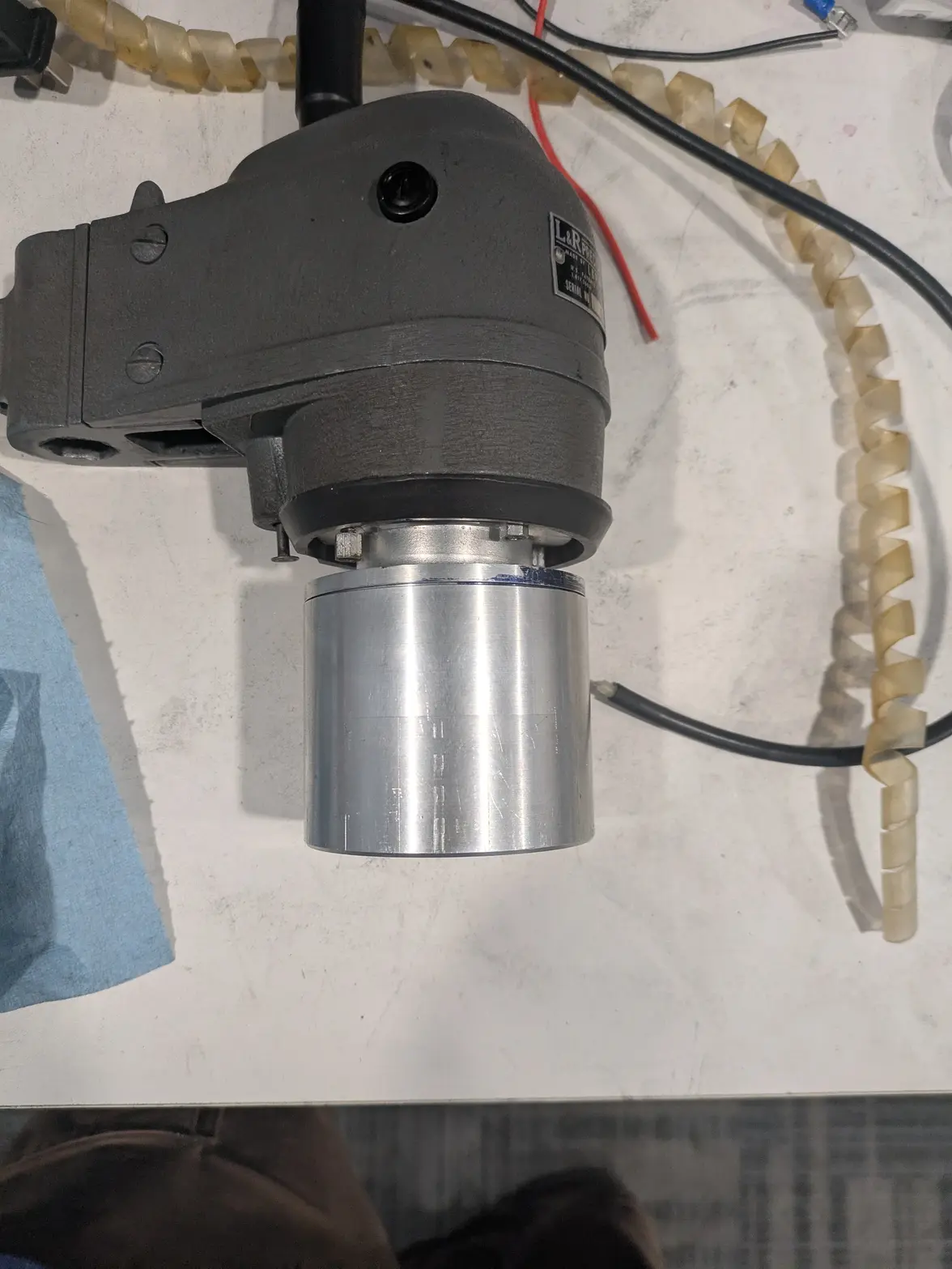
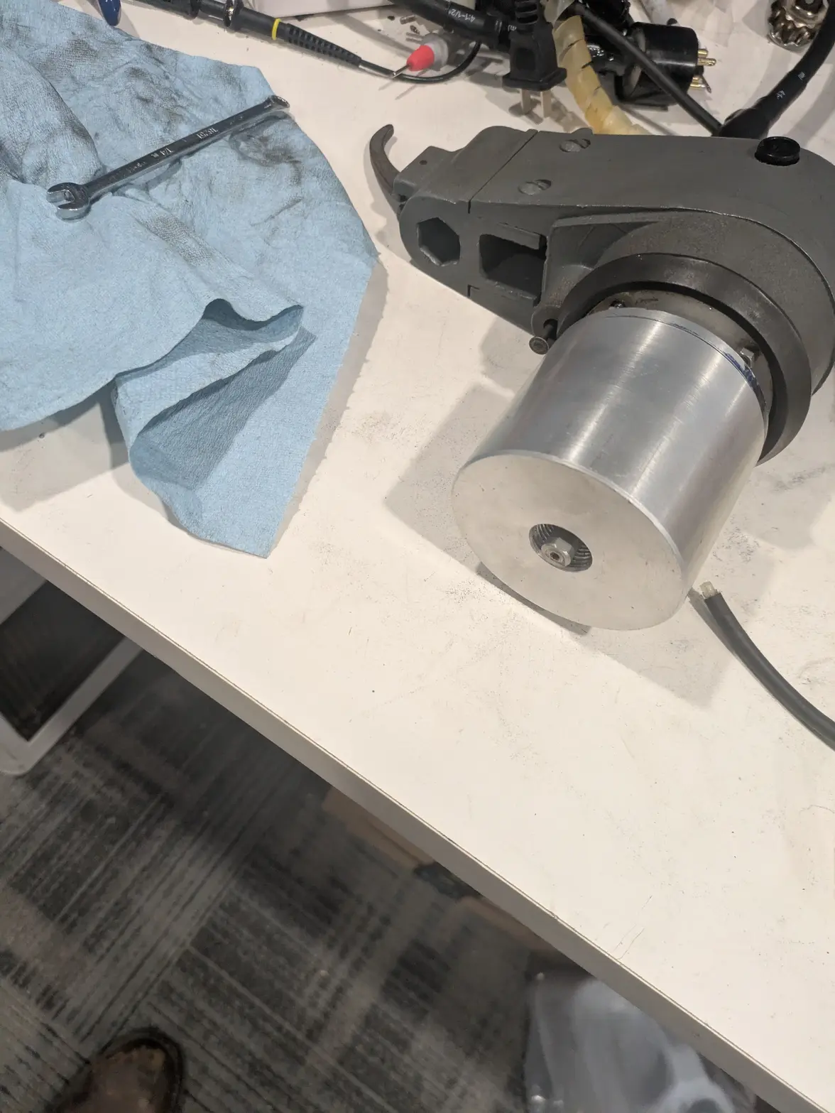
HERE it is assembled on the machine:


You can see the shaft doesn't stick out 'enough'. BUT it sticks out a little! You can see based on this basket holder how much I have to take off:


I BELIEVE I need to pick up another ~0.200" for the clearance I need without modifying anything, which is a touch over 5mm.

FORTUNATELY: I am at 33.78mm for the 'horn' section, and I EXPECT (based on commercial horns) to have the final horn dimension be ~25mm. It is obviously still the big 'unknown' of course but the hope is I'll know whether this was a whole waste soon!

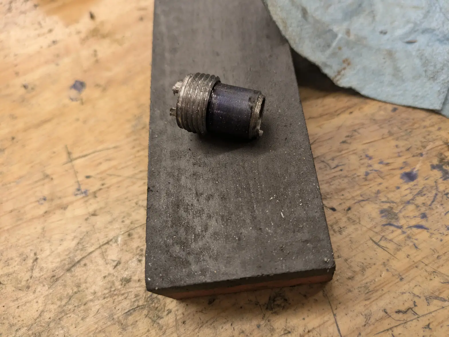
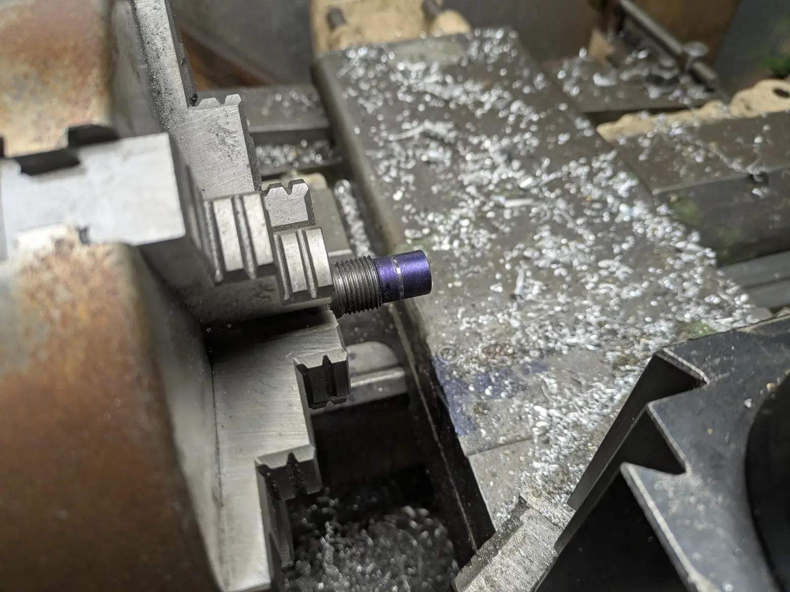
FINALLY for the day, I decided that since the center shaft is 'done', and the 'cup/'horn' just needs cleaning(besides final shortening), that I'd do the last step on it, which is a simple cold-blue: It is the only steel part that will touch the liquid, so it seemed like a good idea:


The cold blue was just some old stuff I had in a drawer, so it wasn't the best stuff, but seems to have done the job.


Overall, a successful night! Tomorrow my task is to get the copper contact plates made (or at least a jig to do so!). Tuesday/Wednesday I'm hopeful I'll have the time to get the piezo rings installed and the cup tuned! I have family coming on Thursday, so I might not end up getting to that point before I have to take a week off, but am hopeful I have the answer to 'will it work?' by then 馃榾
 
Posts
1,086
Likes
1,162
Urgh, managed to screw up making the plates twice tonight. I have a good procedure, just not a good attention span this evening. Screwed it up 2 different ways (the 2nd probably because I was rushing to try to get done by bed time).

SO, whole thing is going to be delayed a bit. Tomorrow is making the plates, then it won't be for another week that I get to assemble it.
 
Posts
17,464
Likes
36,610
Can't you just cancel your family commitments and get on with the project?
We are impatient and need to see progress each day!

馃槈
 
Posts
1,086
Likes
1,162
Can't you just cancel your family commitments and get on with the project?
We are impatient and need to see progress each day!

馃槈
Urgh, I wish 馃榿 I'm desperate to see if this will actually work. So far a ton of work for something that MIGHT work.

I DID make a bigger commitment though, I ordered TWO 'nicer' chinese driver boards off aliexpress. The one I got was the one I could get immediately, but the more I look at reviews of it, and the board it self, the more clear it is that it won't last very long. BUT it'll be good for testing.

AND having TWO identical boards means I will be able to have the 'tank' plug working (though, I can't imagine I'll EVER have a tank 馃榿). Which will be nice since it'll be a spare board for the 'machine' plug if I ever do something stupid 馃榿
 
Posts
1,086
Likes
1,162
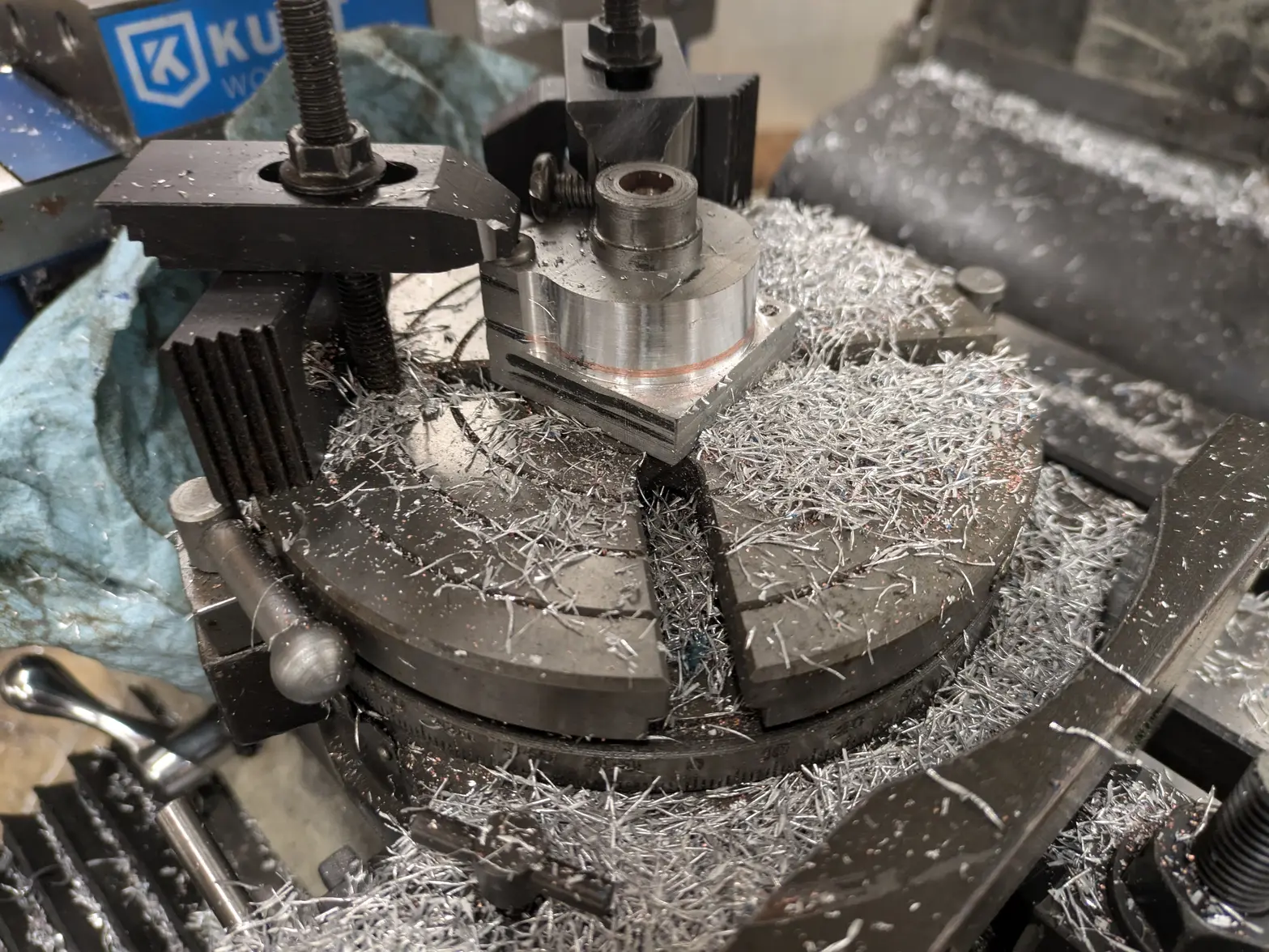
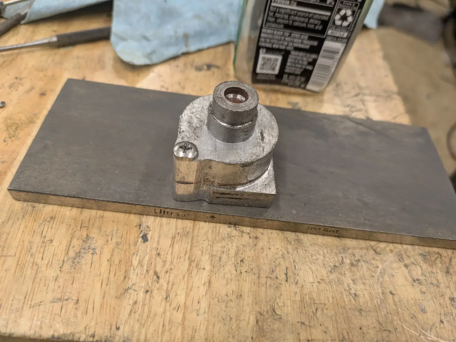
Got the rings done, 3rd try (1st tonight). I made a disposable jig, which used 2 machine screws to sandwich the copper between aluminum.

I then used the boring bar to cut the center hole (what ended up being a little tight, but sandpaper/etc can make up the difference!), the the rotary table to cut the outside diameter except for the bolt holes, where my clamps were.

I moved a clamp and milled the other screw hole part even with the rest of the part, leaving 1 screw in place. A little work on the die filing machine made that not as goofy looking, and the screw hole itself is going to double as the wire terminal.

I didn't take any pictures out of the jig, but these are ready after some fettling.

HOWEVER, UPS managed to delay the ceramic piezos another day, so I can't test the setup at all. To be continued!

 
Posts
1,086
Likes
1,162
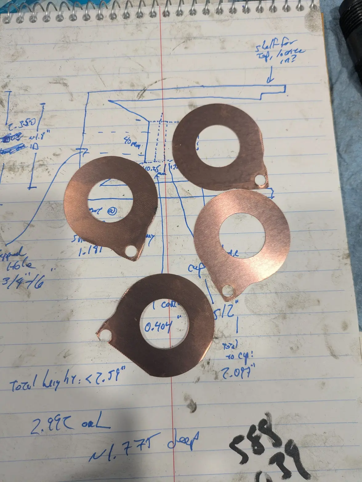
Photo of the plates: I need 1 (or 2) of these, so the fact that the tabs aren't as great (original material was cut a little small in a few places馃檨). But I have at least 1 that is perfect, and 2 more that might work.

The ground is the entire body, so if I can't get a plate to work, I can put a mounting screw somewhere instead.