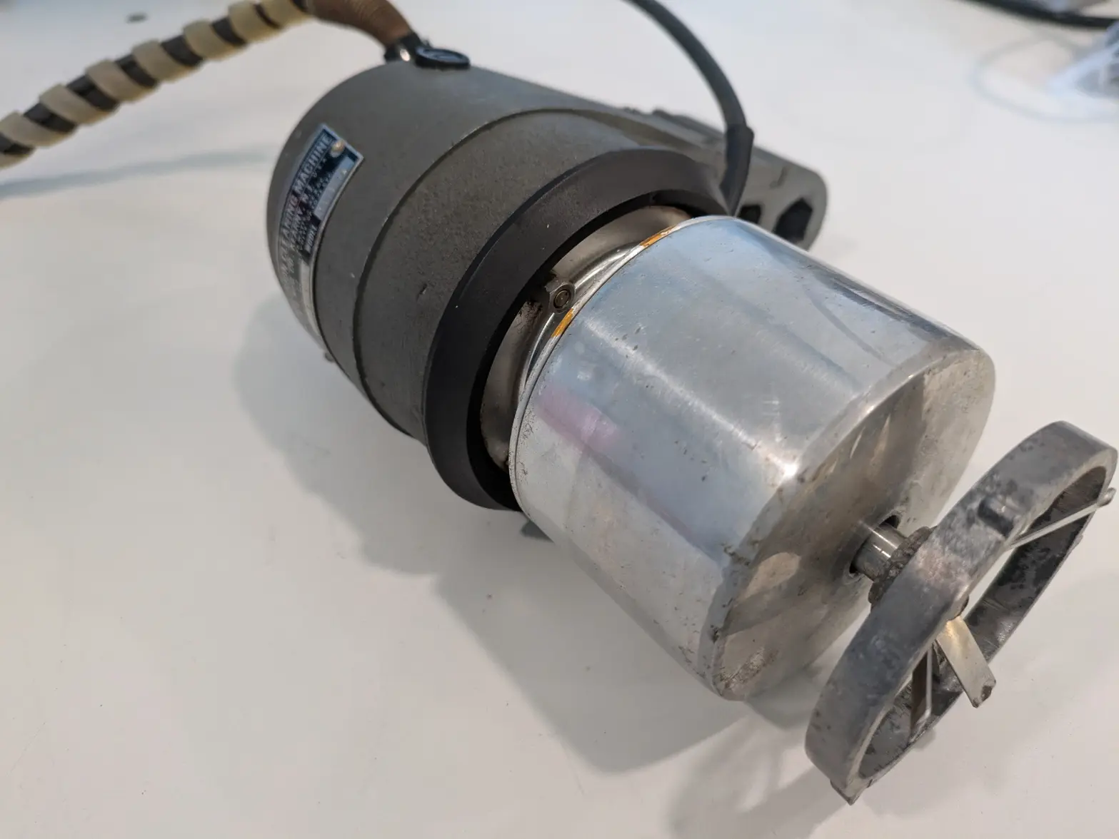
New(old)Tool day! L&R Console Watch Cleaning Machine

Posts
1,086
Likes
1,162
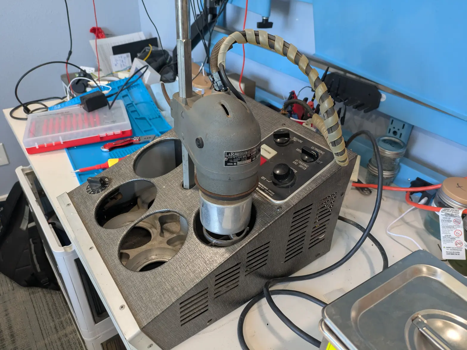
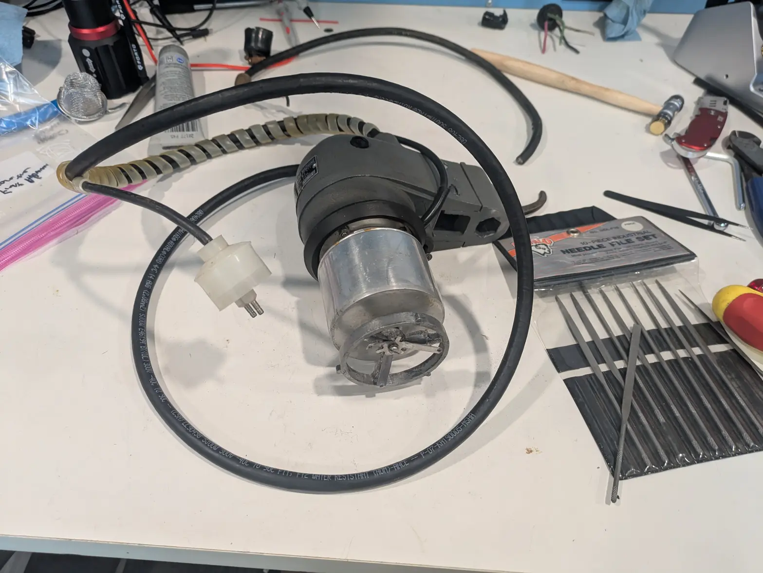
I've been looking for a good cleaning machine for a while, and found this 'reasonably' priced with a 'make an offer' on Ebay, and it finally showed up today!

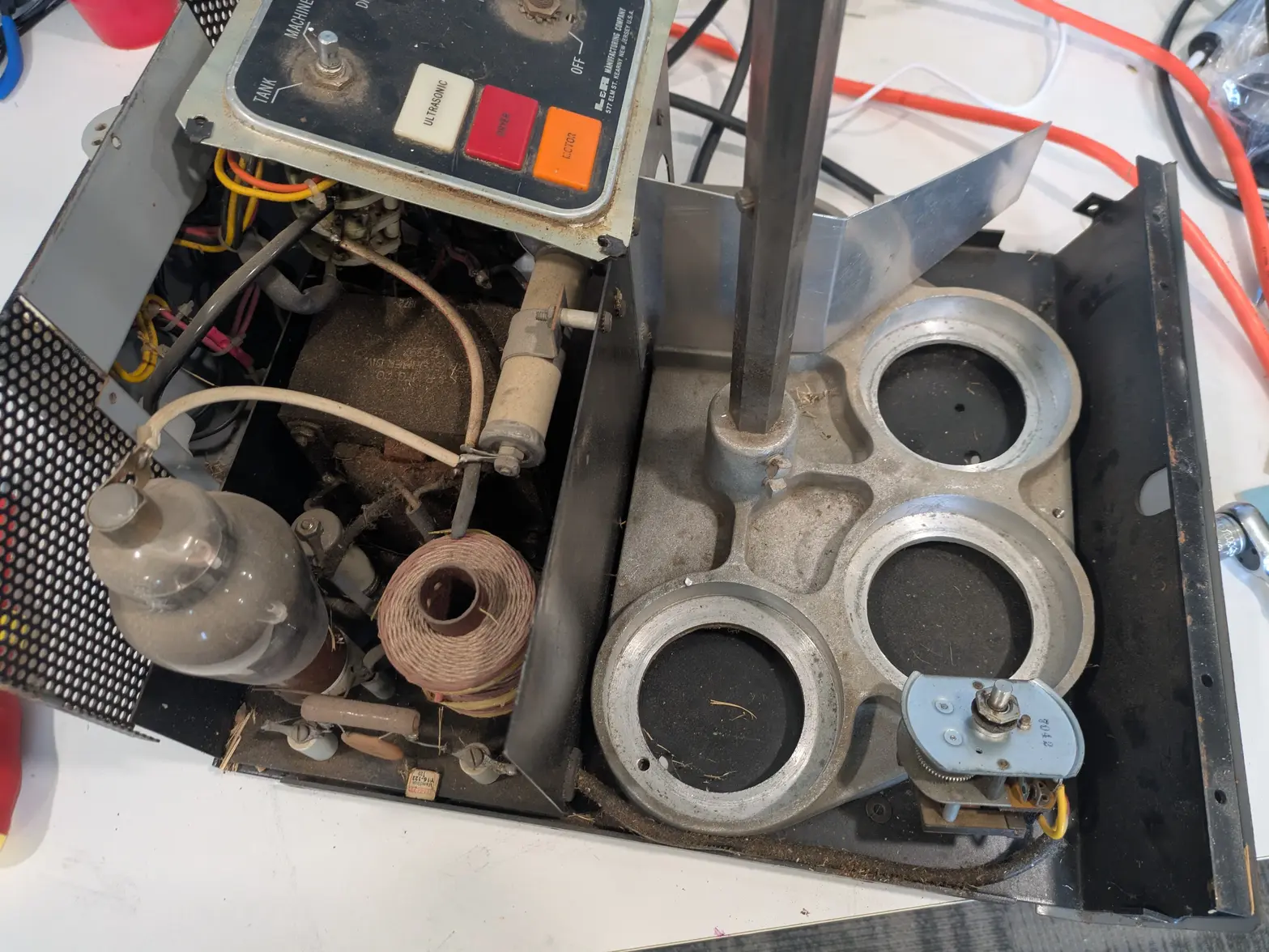
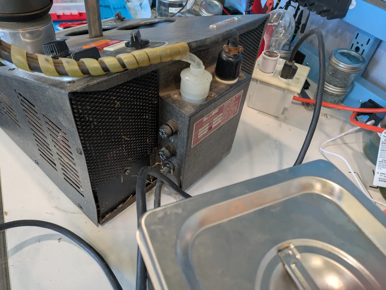
It is a L&R Console machine, sold 'as is', and mentioned that the motor worked, but the ultrasonic did not. I pulled it out and gave it a shot under a dim-bulb tester, and found that the ultrasonic AND heater/fan didn't seem to work, AND the motor only worked when all-the-way on. AND the motor didn't do the auto-reverse even when the button was depressed. Looks like we've got a heck of a project 馃榾

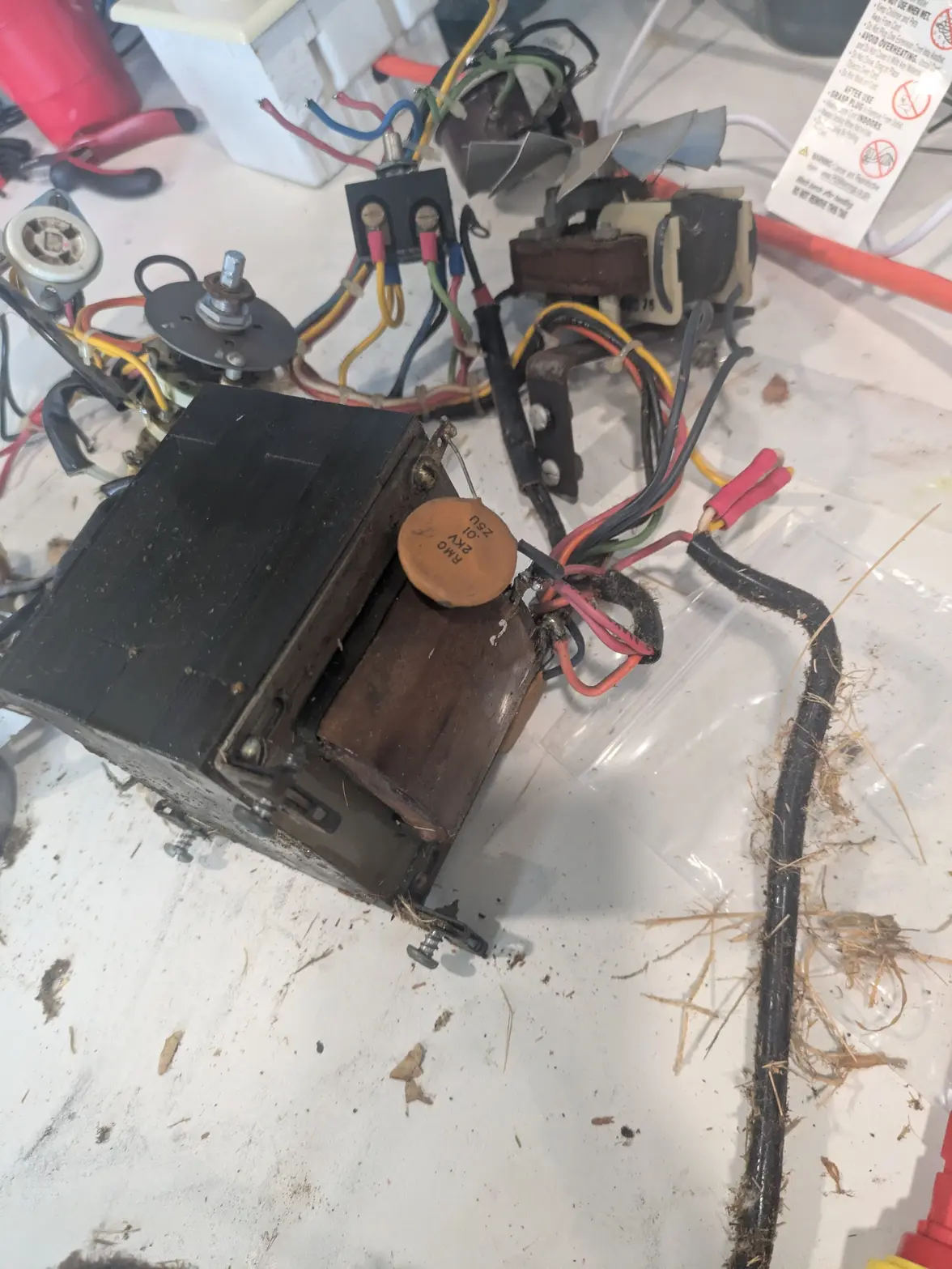
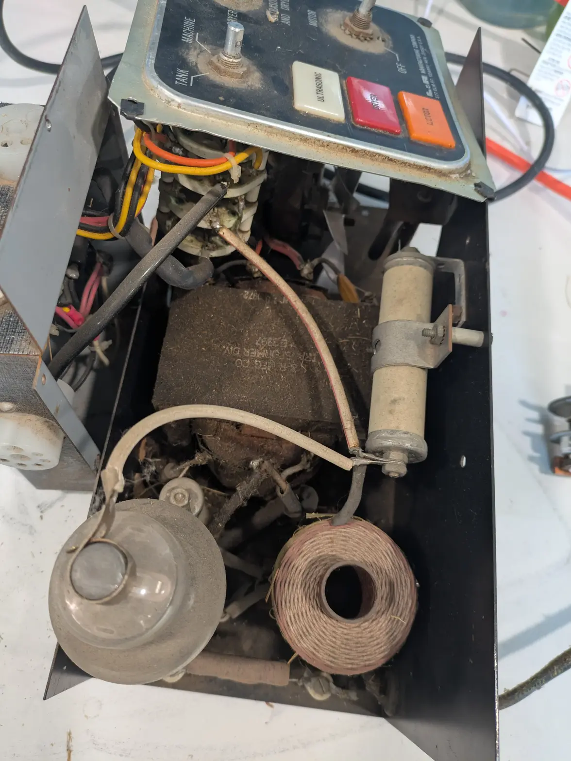
I spent a few hours disassembling it today. I took plenty of pictures, and have to figure out what needs repair. I presume all of the switches dirty/need cleaning in SOME way, and I'm sure there are some other components that need help. My next step is probably going to be to give it a good clean, and try to figure out the wiring diagram. The machine is FILTHY, there is grime and grossness all over the machine, plus some grass, webs, and bugs throughout. I'm guessing this lived in a barn for a while. I ALSO haven't even dug into the head, where the motor and transducer are. The brushes no doubt need some TLC, and the wiring that goes into the head has a busted grommet at least, so I'll have to poke at that as well.

Anyway, a project begins!
 
Posts
1,086
Likes
1,162
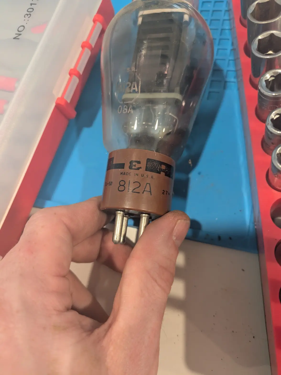
Also, forgot to mention 馃榾 I've already ordered a replacement vacuum tube. Fortunately they are pretty common/popular for guitar amps (812A), so they are pretty cheap if I don't want audiophile quality 馃榾

Mine is the original L&R, but I'm concerned as it has a burn mark on the side of it.
 
Posts
365
Likes
454
If it鈥檚 inside the tube, it may not be a burn mark but the getter (oxygen scavenger) used to prolong tube life.
 
Posts
1,086
Likes
1,162
If it鈥檚 inside the tube, it may not be a burn mark but the getter (oxygen scavenger) used to prolong tube life.
Hmm... It is inside the tube. But looks like something bad? You can see it in this photo, what do you think? See the lower right of the tube.

It is an original L&R labeled tube, so it would be amazing to use it ...

 
Posts
1,086
Likes
1,162
SO, I spent a few hours re-flowing solder, replacing a couple of wires, and cleaning/lubing all of the switches. AND, it looks like of the 4 'powers' of the machine I've figured out:

2 work! The heater and motor both seem to work perfectly!

1 Doesn't work: The fan, despite getting 120v doesn't seem to spin. I might de-solder it and take it apart to see if I can fix it, else a 120v fan is cheap, and I can make a bracket to mount it easily enough.

1 unsure: I don't know about the ultrasonic, I didn't really test it. BUT I definitely heard a distinct 'hum' from the transformer, which makes me thing SOMETHING is happening. I can fire up my oscilloscope to figure out if it works, including the old vacuum tube. I'm definitely optimistic!


So next steps; I have to finish assembling the base, but first I have to pull out the fan and do some work there. I have to figure out if the ultrasonic works. THEN, I have to rebuild the head. The auto-reverse doesn't seem to work, neither does the 'button' output from the head, so I suspect there is a problem there.

Overall, just spin + heat seems like a pretty good win so far 馃榾
 
Posts
17,464
Likes
36,610
Enjoying this one Erich, keep us all updated.
 
Posts
1,377
Likes
2,802
Serious old school repair stuff 馃憤 i hope it will work again soon.
 
Posts
94
Likes
116
Loving this thread, and it's a great machine when it works, I used to have access to one.
 
Posts
1,086
Likes
1,162
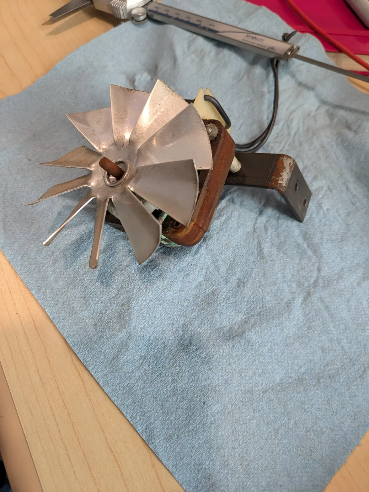
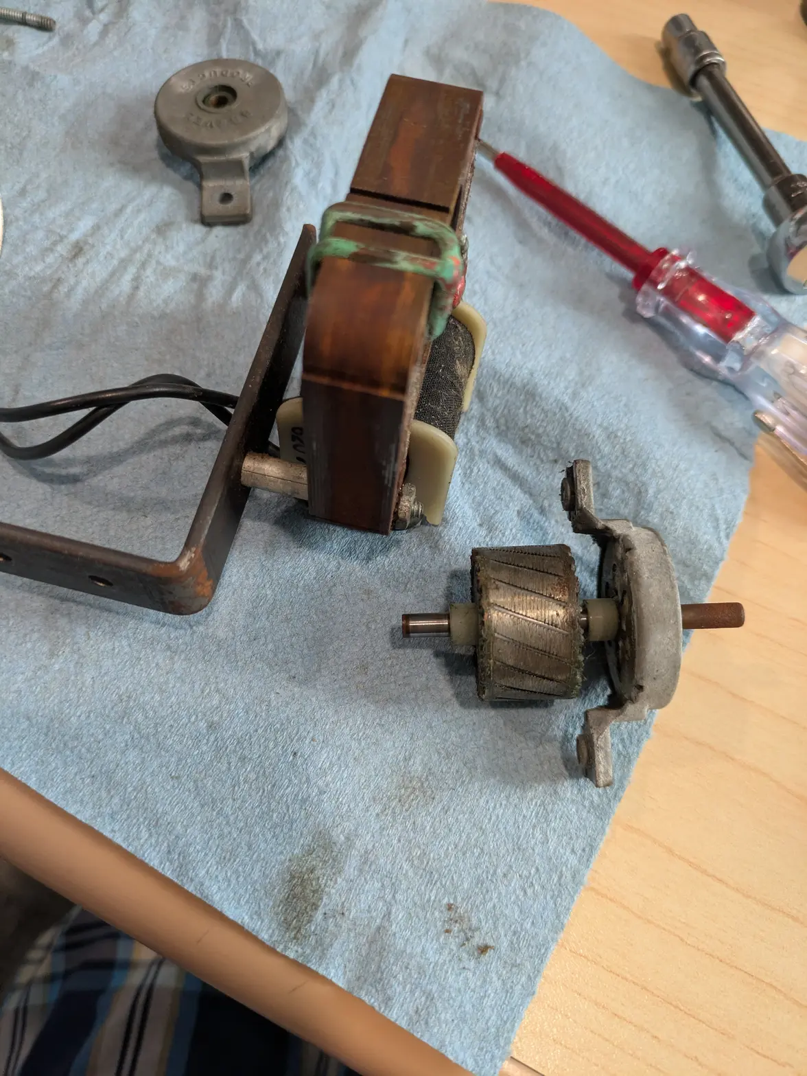
I spent a little while pulling out the fan. The coil itself seems to OHM out, though pretty low at 33Ohms (which would be ~3.6amps! When this shares a 4A fuse with the motor & ultrasonic). Also, it isn't clear what is wrong with it, and it is crusty, so I'm just as happy to see if I can rig something to replace it.

However, I found that this style of motor is pretty common in bathroom vents! I ordered this one, more or less the lowest-amp-draw version I could find that would be here tomorrow:

https://www.amazon.com/dp/B08LNTPH7N

Its a touch taller, and doesn't have the bracket-mounting bolts, so I have to figure out if that height is problematic (I guess it is 'width' the way it is mounted? It is 4mm further from the edge of the case, but I doubt that is meaningful. The mounting-bracket is going to be more challenging, I might have to figure out

Also, it has a longer shaft, which I can either cut or leave, I don't think that part matters.

I THINK the bolts that hold the commutator bracket are intended to be the mount, so I might be able to make something based on using those. Else. Maybe I can drill it easily enough...

 
Posts
1,086
Likes
1,162
SO, while I wait for a replacement fan, I decided to pull apart the head. I took quite a few pictures, so I'll share some of them here 馃榾

Here's the head. I did a bit of a disassembly on the basket holder first, as it needs to come off, but that happened between photos.


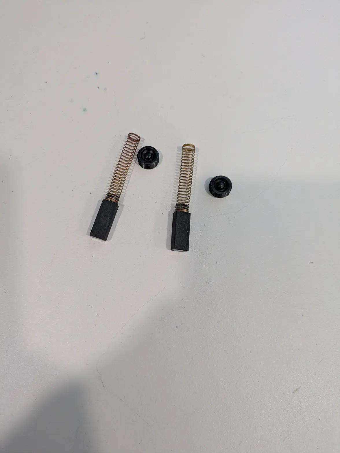
Brushes removed, seem to have plenty of life left!


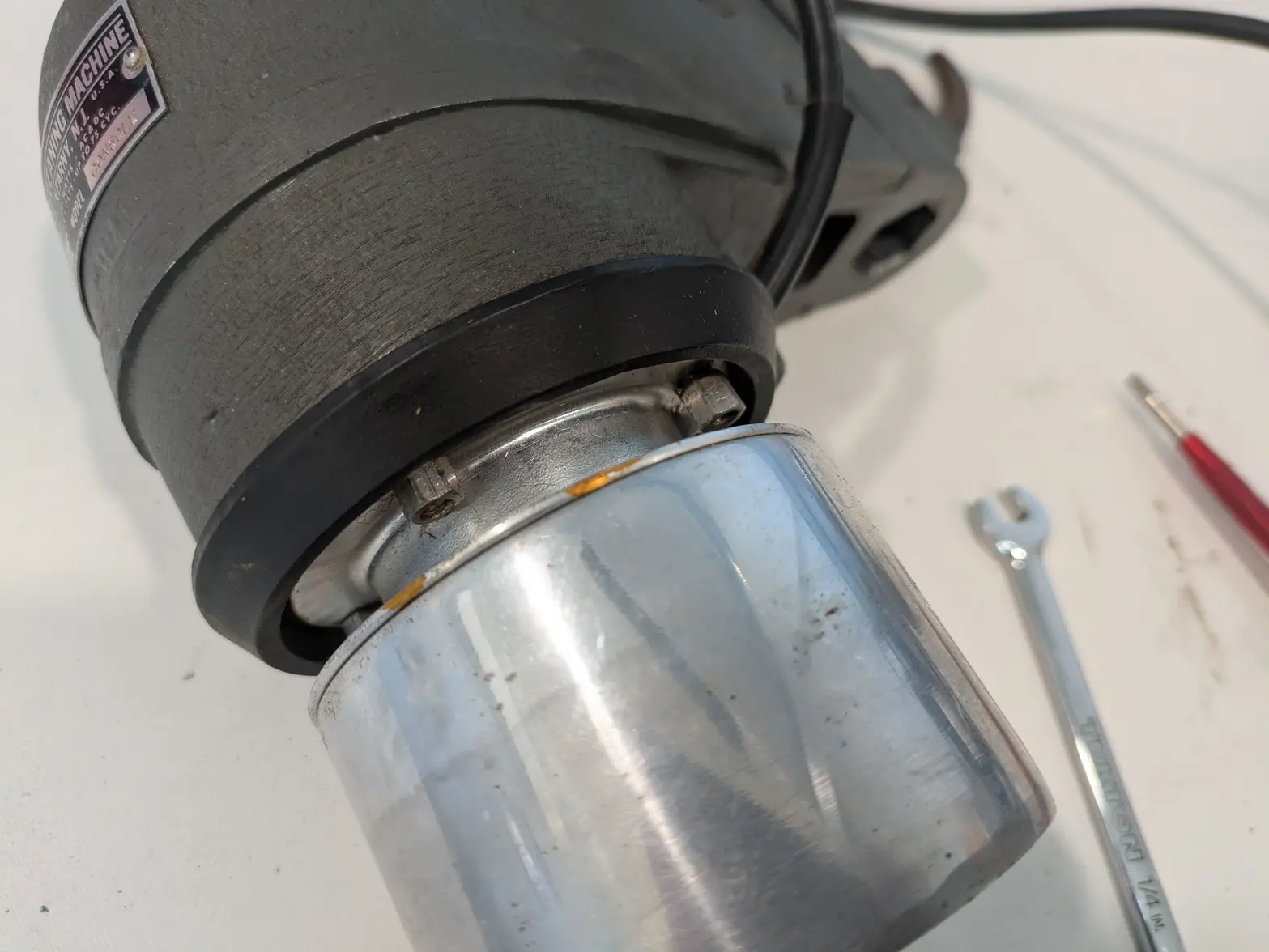
These 4 elongated-nuts hold on the transducer for the ultrasonic.


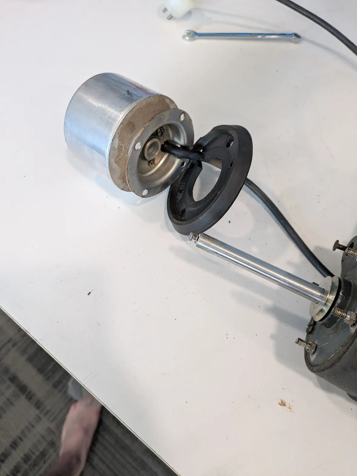
When removed, the whole thing, including the wiring comes off pretty easily! It disassembles further, but I didn't do anything about that as the wire for it is in reasonably good shape, and it likely works.


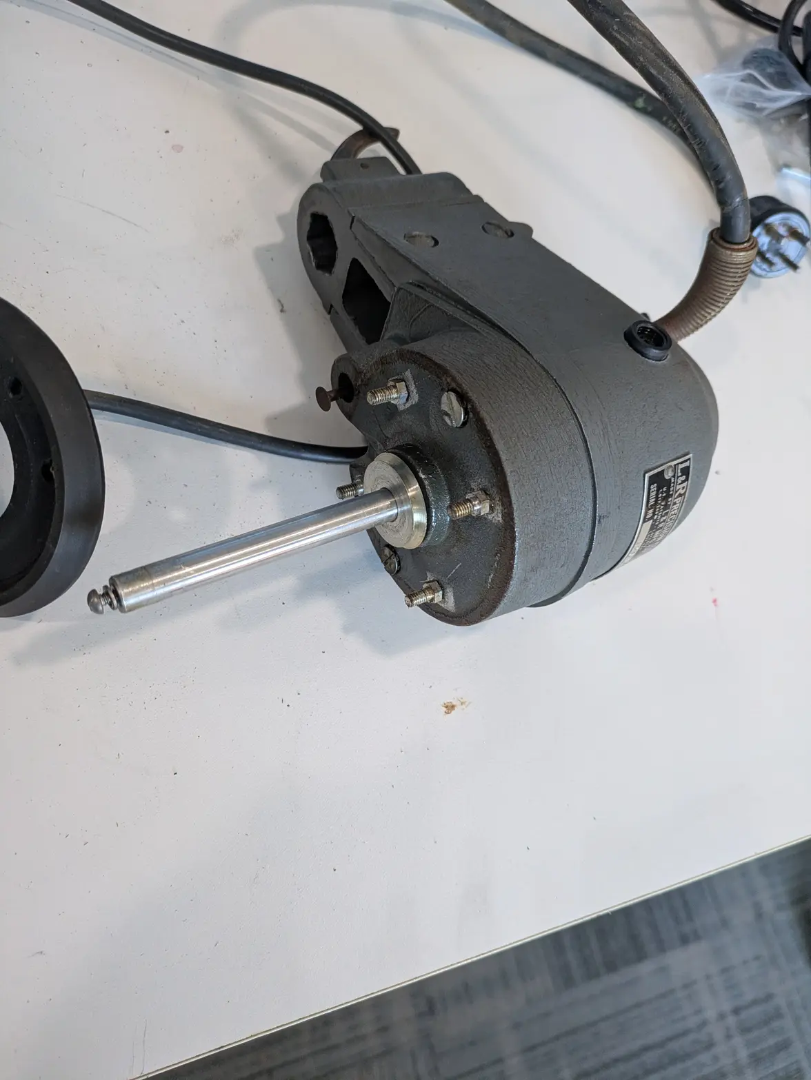
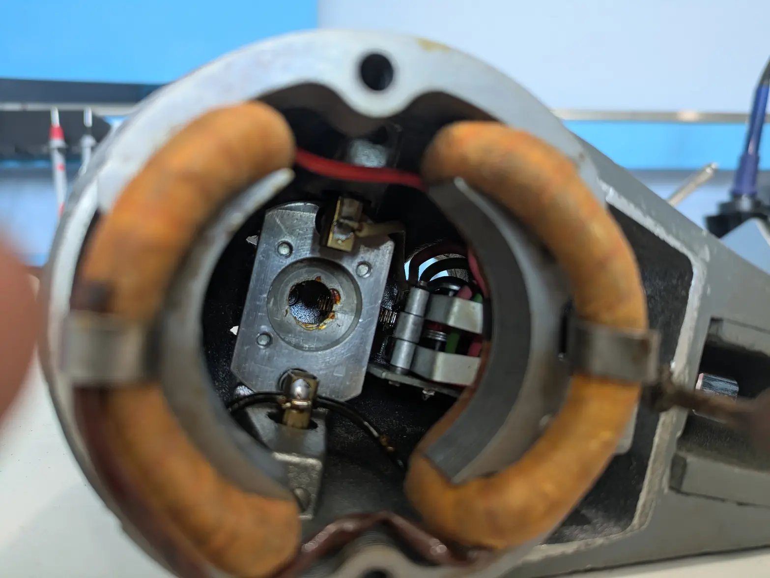
On the other side it leaves behind this. I pulled the stud-things too because I didn't know what was going on, but the flat-head screws are all that holds the bottom of the motor shaft on. With some aggressive tapping I was able to get the 'top' bearing to pop out of the motor housing. It isn't clear to me what that aluminum pulley looking thing is though, I don't see the purpose it serves?


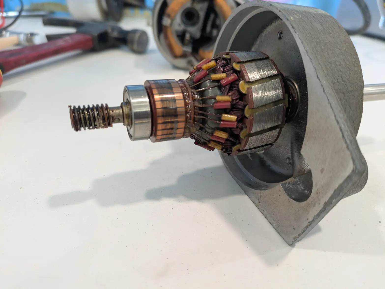
Here is the commutator, windings, and top bearing. At this point I was awfully confused by what was going on at the top. That threaded section seemed really weird, but that'll be explained later! Fortunately I gave up after cleaning it.


Inside: There were studs that held the magnet/windings together, which I was able to pull out easily enough.


And here you can see the flat-heads that were UNDER the studs which acted as brush-holder screws. I ended up NOT desoldering the brush holders (I was having a heck of a time getting it to melt!), so I instead tapped the brass parts out of the plastic, which worked well enough.


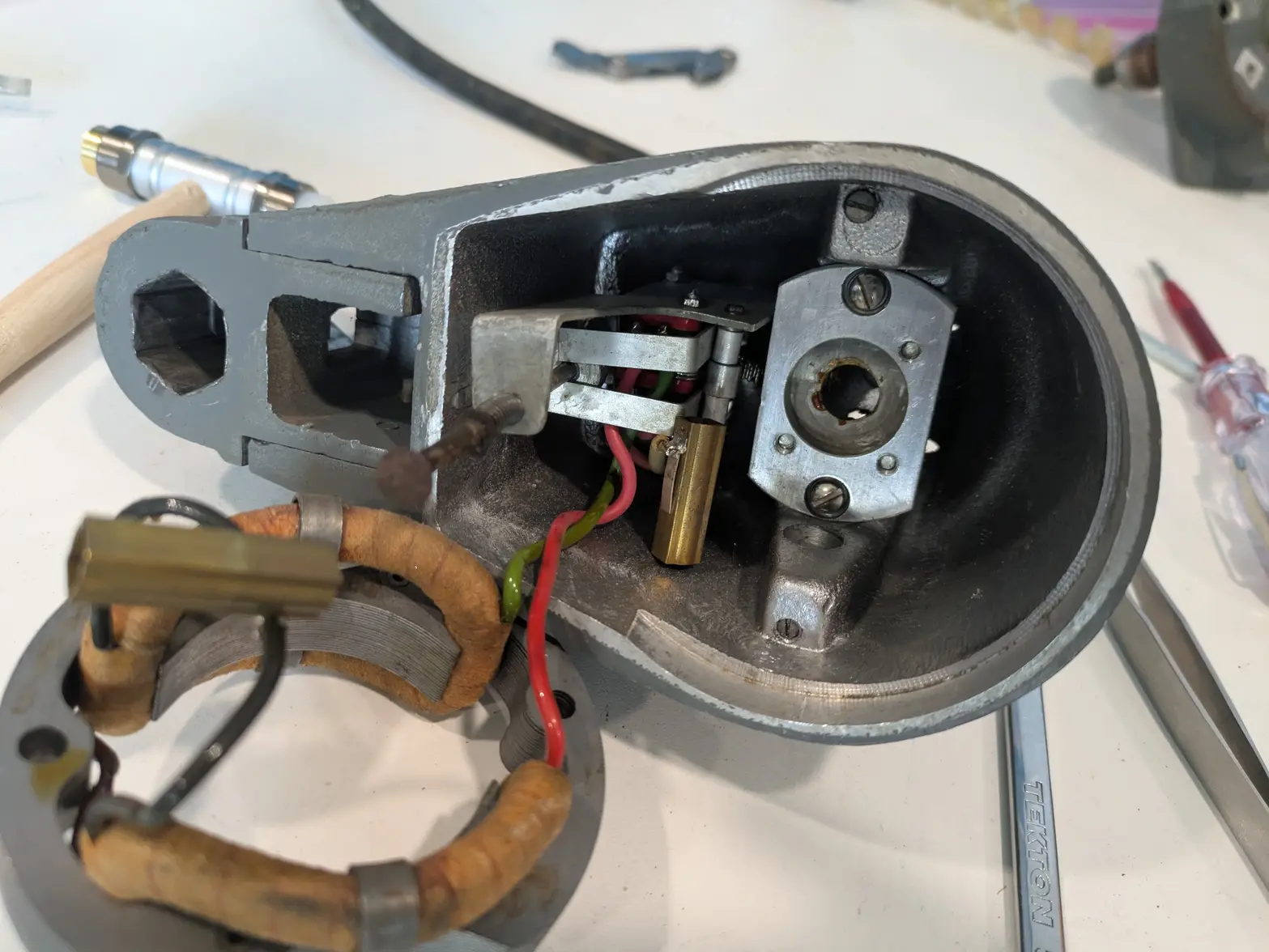
At that point, the two screws that surround the bearing are all that holds the rest of the head together. Removing them results in:


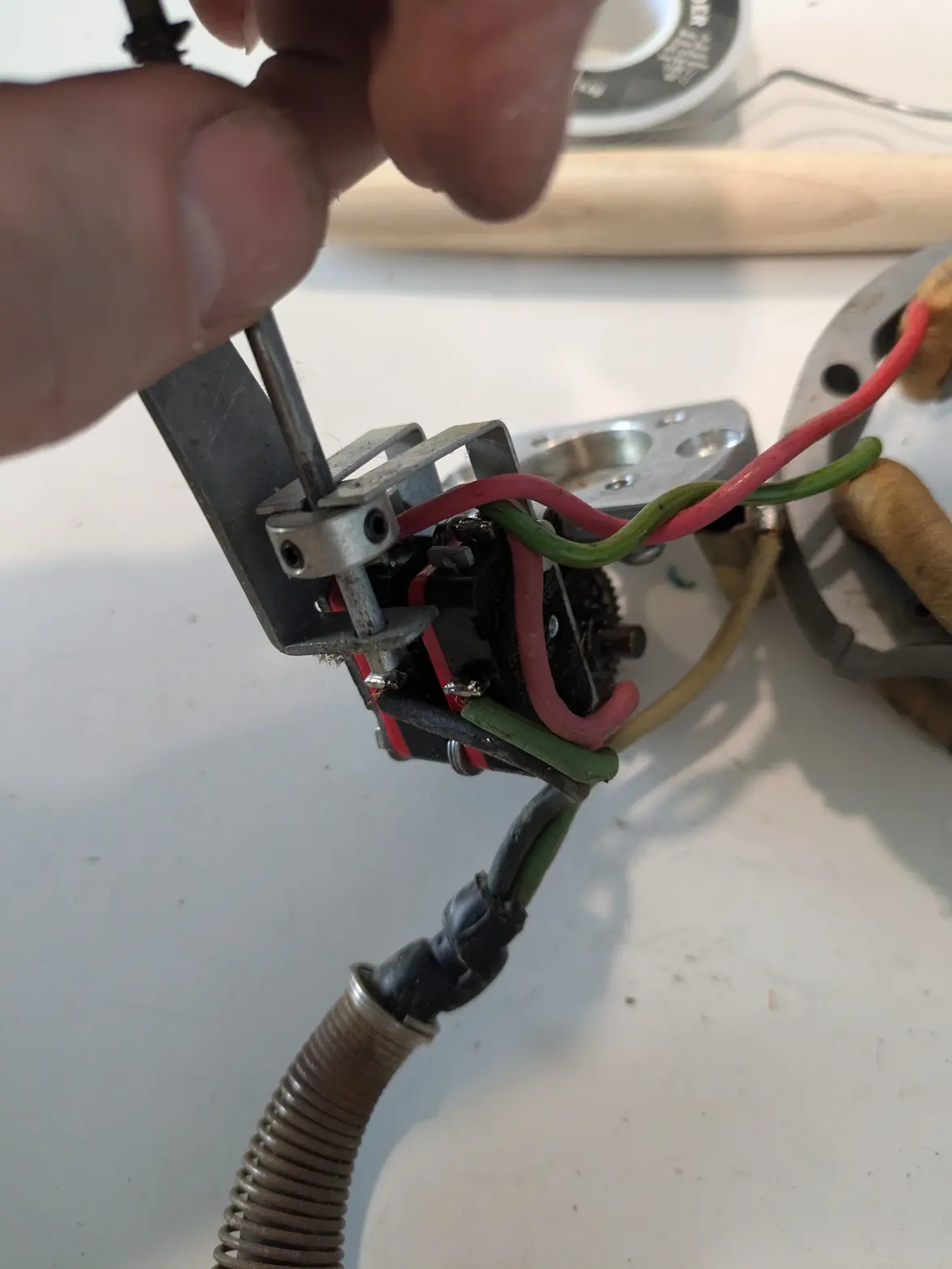
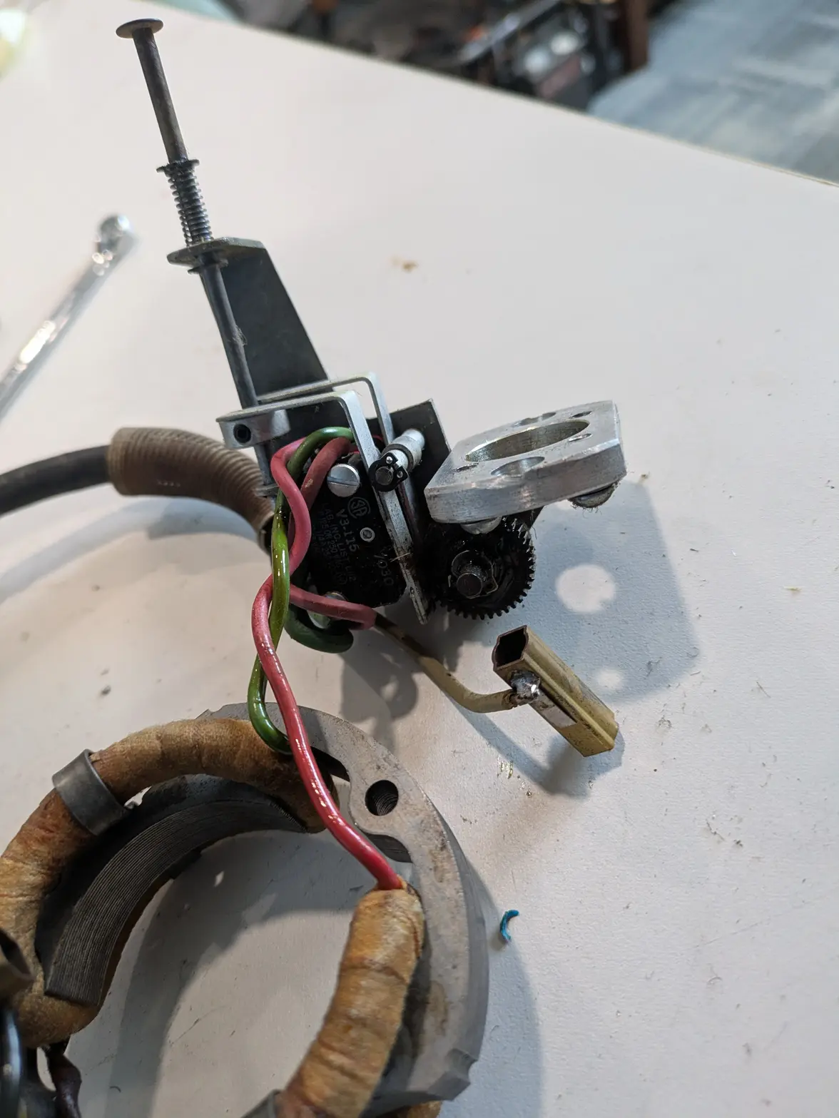
This is a pretty neat little mechanism! It uses a pair of microswitches to do 2 tasks;
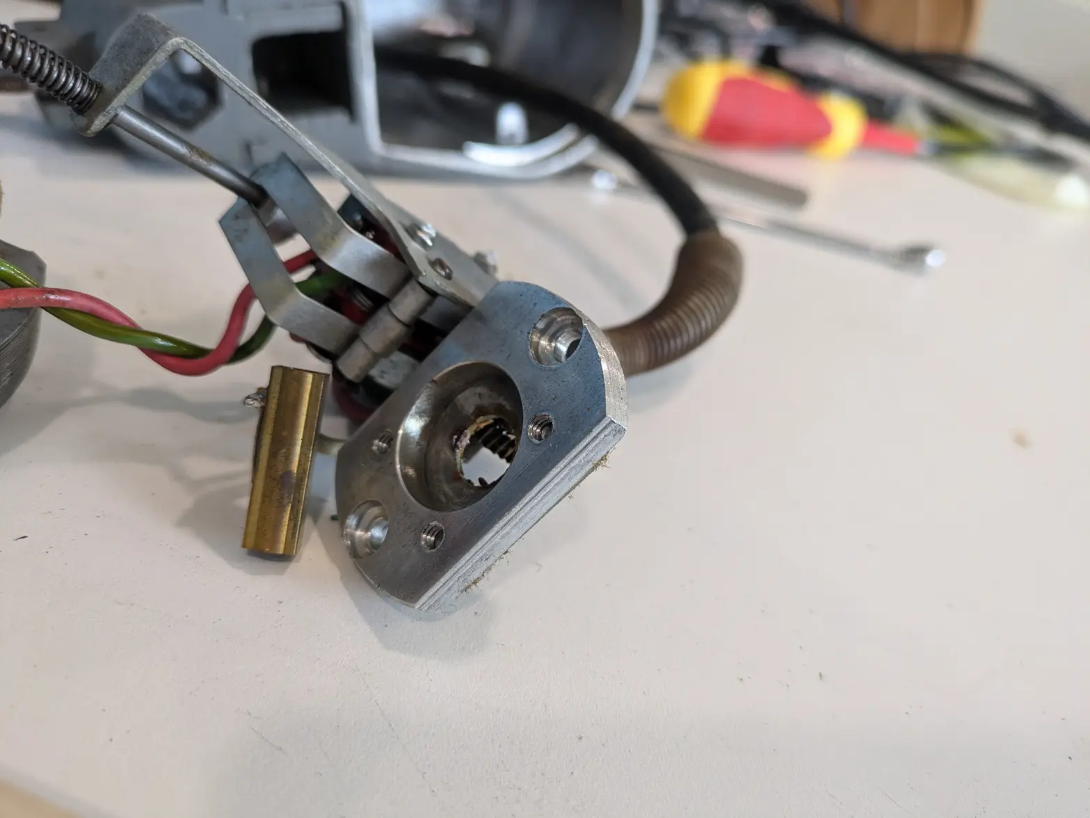
1- Set the 'switch' as connected so that it turns on the ultrasonic. The little plunger switch you can see on the bottom of the head touches the top of the jar, so the ultrasonic will only turn on if the head is 'down' against the glass. You can see the plunger on the top-left. The plunger 'releases' those two aluminum arms so that the switches can be released from the looks of it.

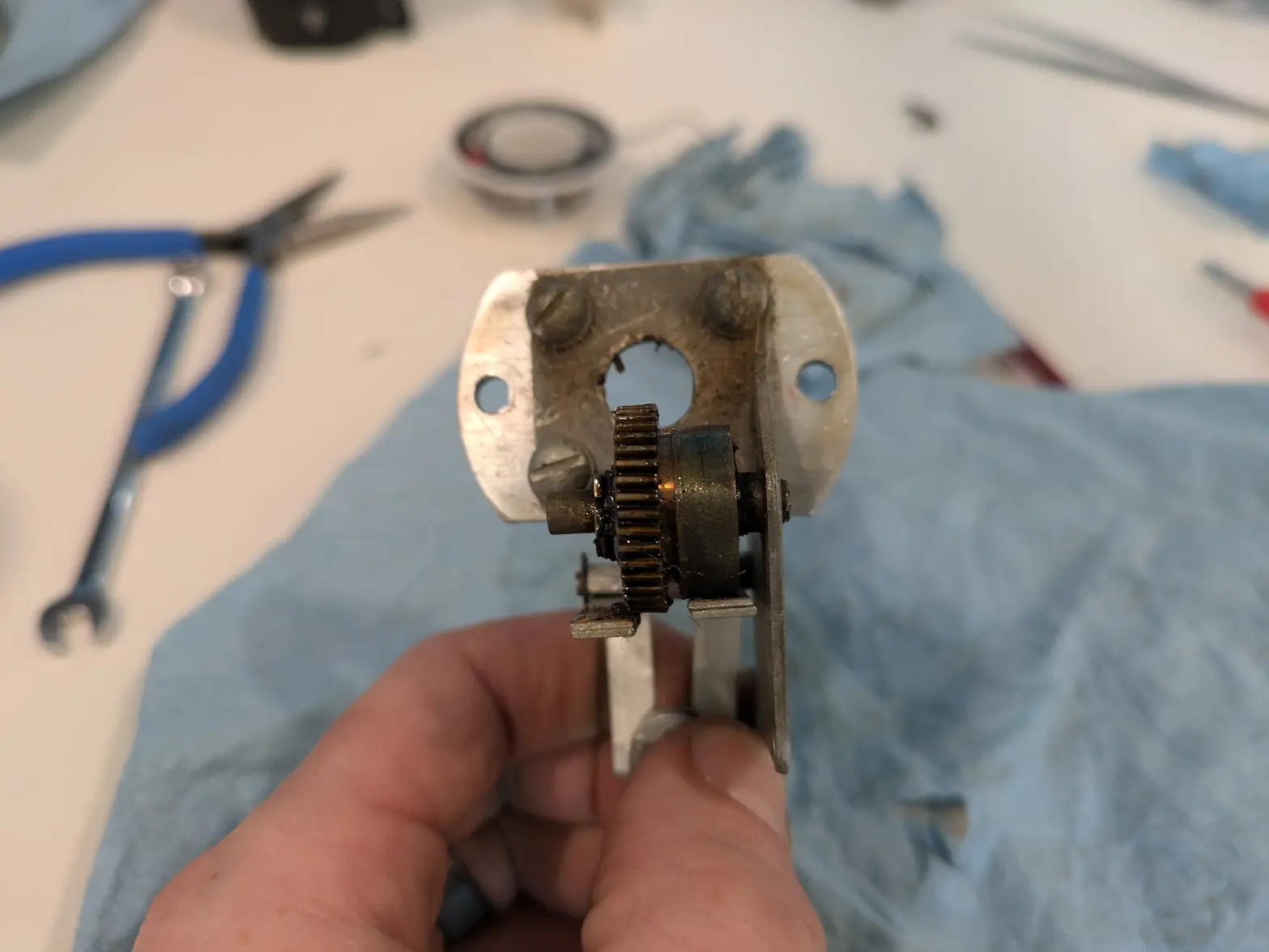
2- Switches the motor direction. There is a little cam on a gear that interacts with that top threaded section I didn't understand that rotates a gear with the cam, and switches the motor direction. Note that this ALSO only works if the plunger switch is 'in', as it is supposed to stick to 1 direction outside of a glass as well.


Here you can see the plunger/arms a little better. The plunger itself seems reasonably free, but the aluminum Ls aren't. They seem tight, so I'll have to disassemble/inspect those as well.


Another side:


One problem seems to be the alignment here. I can't figure out how the gear is held on, but the teeth need to be between the two aluminum blocks, which don't really have an adjustment.


Overall, a productive/simple look here! I suspect my ultrasonic is going to get to play with a few parts here. It is a little disappointing as someone has obviously been here before me and done a so-so job in the head, but at least it works!


ONE BIT OF HELP I could use:

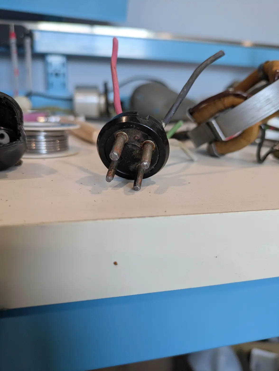
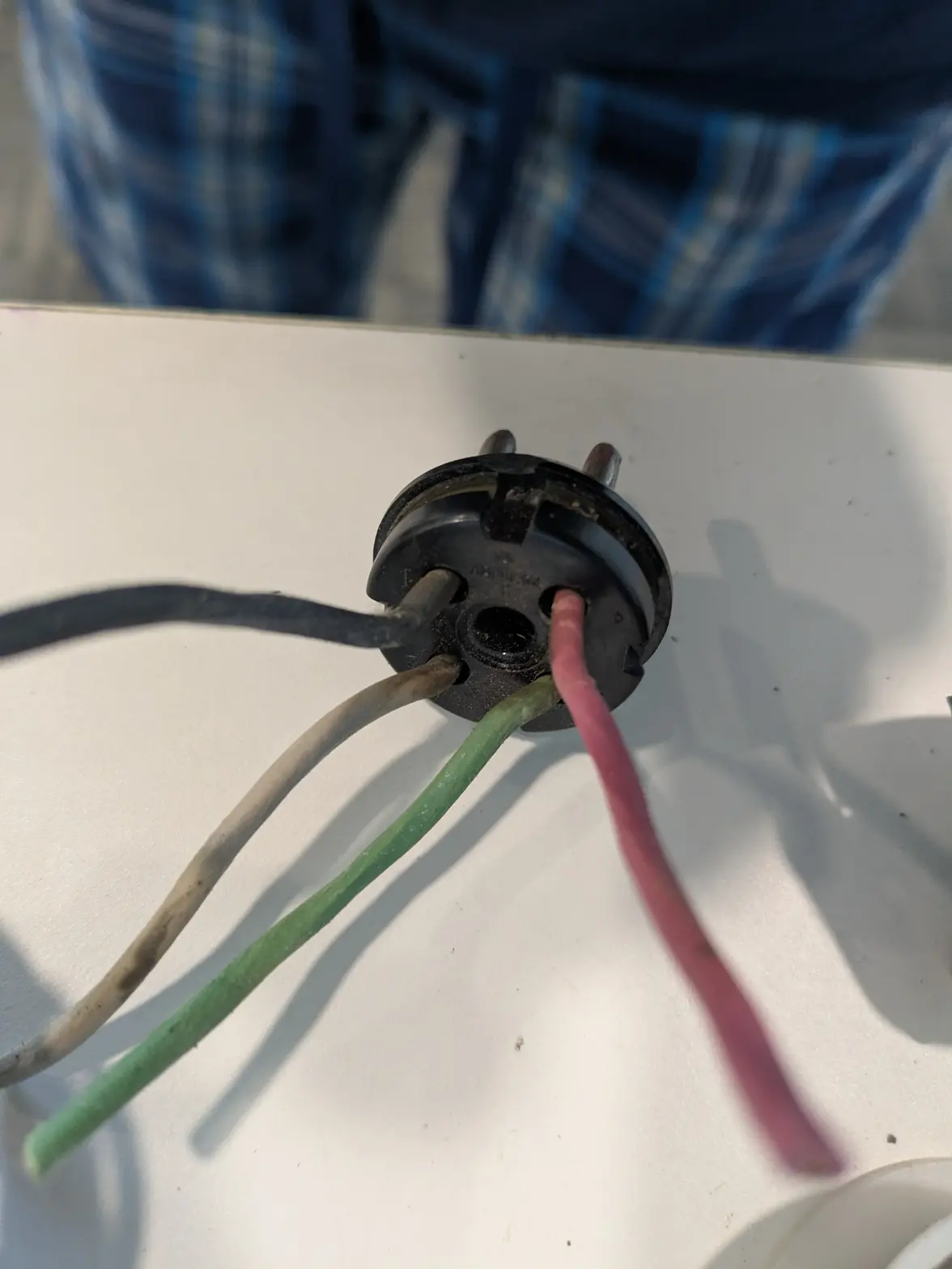
I tried to take the plug apart and it is really brittle, so I'm not going to be able to re-use it it looks. It IS not the original (someone else has been in here before!), so I was wondering if anyone has an idea where to find a replacement end-plug? This actually ends up being the male-end identical to one off of a 4 pin 811/812 vacuum tube!

 
Posts
1,086
Likes
1,162
SO! I managed to find this! https://www.ebay.com/itm/197106778189

I ordered it! I figure, worst case I can just use that, solder in everything, and fill the case with epoxy when I'm happy with it to create a cable-end.

It probably wont' show up until next week, so no progress until then on the head. Hopefully the fan shows up tomorrow and I can do some work on it while I wait.
 
This website may earn commission from Ebay sales.
Posts
1,086
Likes
1,162
Another update! A trip to Home Depot got me all the stuff I needed to get it mostly back together.

A new wire and some washers, plus some "adjusting" of the switch lever bracket, and I think we are all back together!

I still need to figure out a strain relief for the top, plus get the wiring done, but then I can test it.

Next task is the fan in the base however.

 
Posts
1,086
Likes
1,162
I think it鈥檚 time for an avatar.
I chose a different one, but you've mentioned it to me (or near me?) enough times I finally got an avatar 馃榿


As an update, I got the new fan motor in. I screwed up mildly drilling out the mount holes (the new ones are crimped together, not bolted!) and delaminated some of it, but I was able to get the bolts together, and the fan now works!

I checked the clock-switch, and it seems to work now too! According to my white speedy, it might be a little fast (11:06 when set to 12 minutes), but works!

So now I'm down to waiting for shipping on:

1- A tube-socket, expected 7/29! I've decided I'm going to solder into it, then use an epoxy on the back to just 'pot' the wires into place.

2- Wire strain relief for the head: I have some ordered to come tomorrow. If I can't make them work (they are plastic clamshell ones!), I can always use some vacuum/fuel hose and a zip-tie to mount it into place well enough. I'm not concerned about finding a solution here, but it would be nice to have an OTS one.

3- Vacuum Tube; I'm not convinced mine isn't working, but I have one on order anyway. It should be here by EOW. I'll probably wait to test the old one until the head is back together, unless I get antsy馃榾
 
Posts
1,377
Likes
2,802
Excellent progress and surprising the 4 plug was so easy to find !
 
Posts
1,086
Likes
1,162
SO, while I'm waiting for the tube bases (basically they are parts of a vacuum tube I'm going to modify into a plug!), I decided to do a bit of a function test.

Looks like the motor/heater/etc all works. From the base's side, the ultrasonic seems to work (including the vacuum tube lighting up!) but ONLY if the head is plugged in, and ONLY in 'tank' mode. I suspect I have another problem with that stupid Tank/machine switch.

I'm tempted to remove the ultrasonic selector-switch entirely (though leave the switch in the head active) as well as the 'tank' plug. BUUUUT that probably means I should entirely remove the ultrasonic side of the electronics and replace them with a modern driver. So I am probably going to just 'get it running'. Hrmph.
 
Posts
1,086
Likes
1,162
Oooof. Looks like the ultrasonic is dead 馃檨

I fixed my wiring problem in the base, it actually ended up being an easy enough fix (a broken wire on that stupid switch).

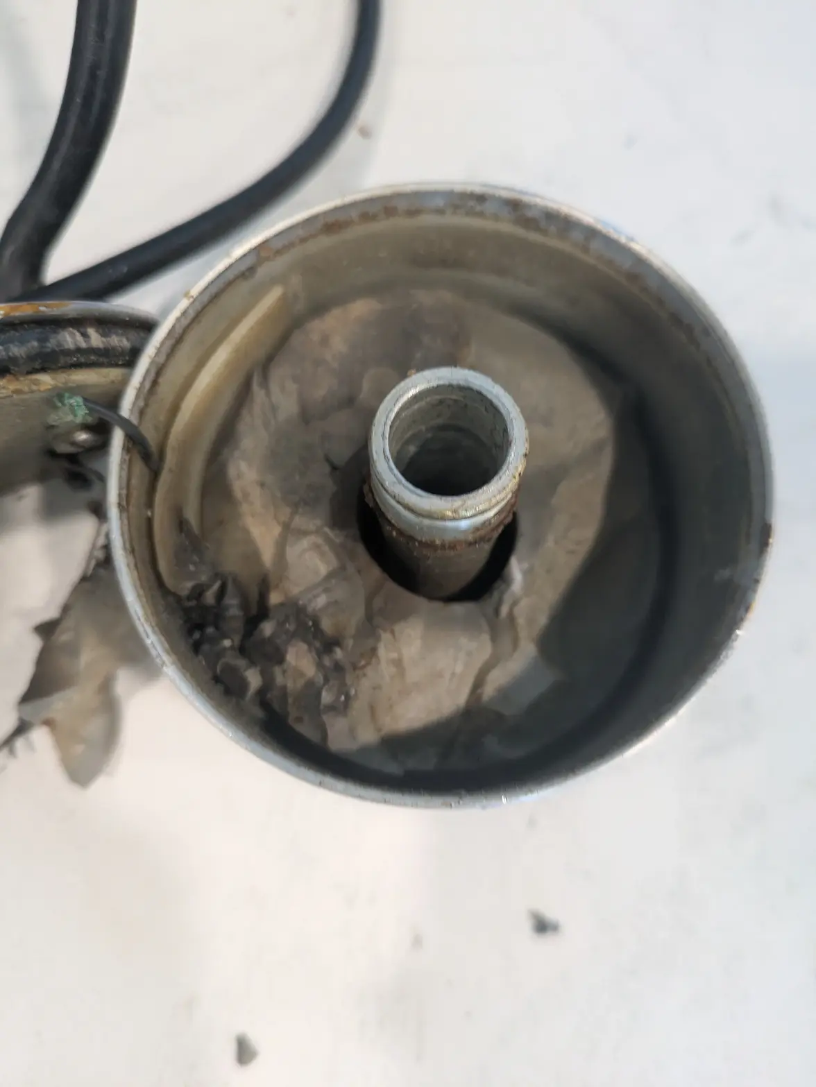
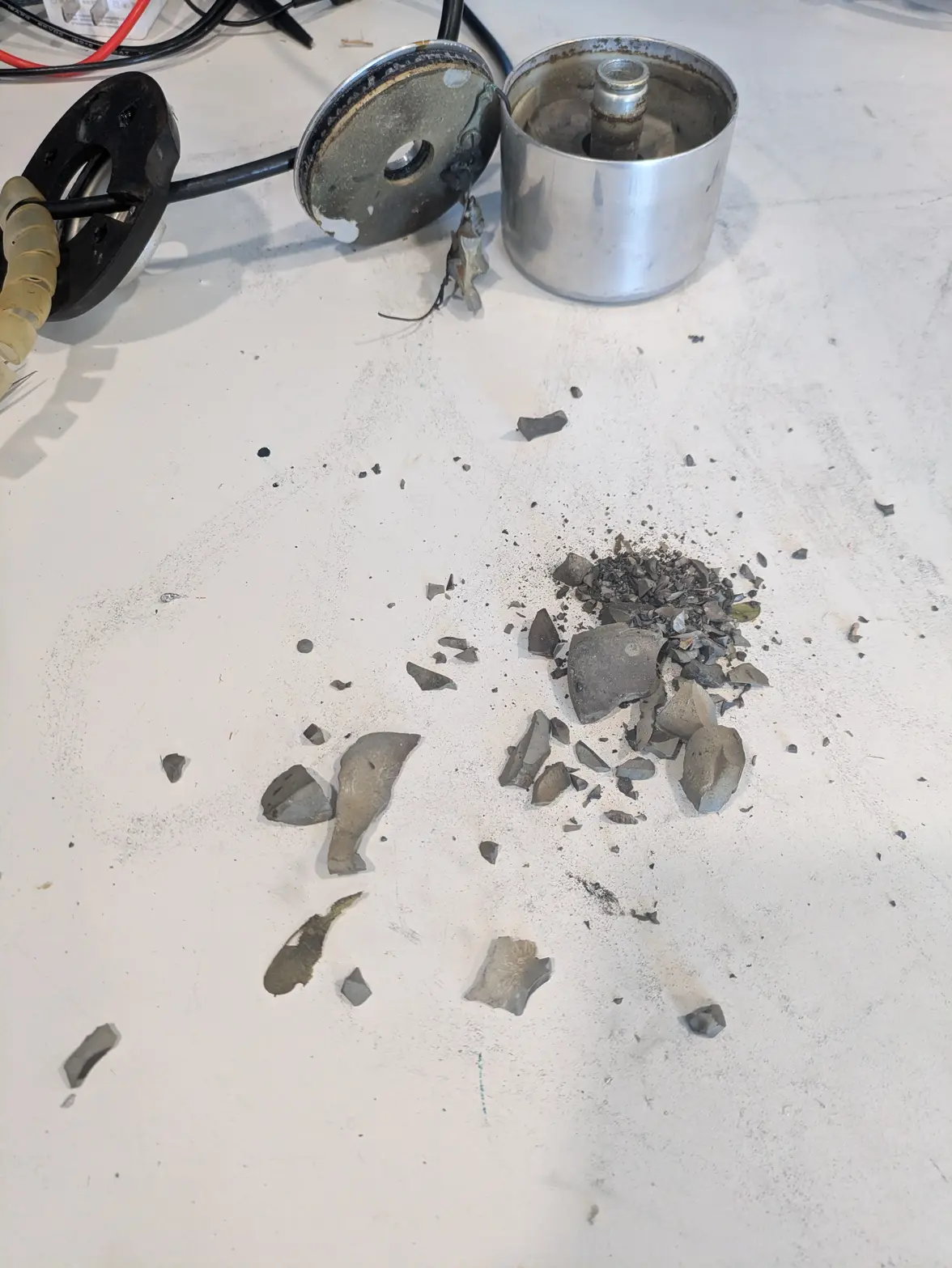
But. I still wasn't getting a bunch of cavetation. So I pulled the US head apart, and I have gravel instead of a transducer 馃檨

 
Posts
1,086
Likes
1,162
I spent much of the afternoon thinking about it, and am pretty sure that there is nothing 'factory' I can do with this, so I'm going to try to replace the whole ultra-sonic setup with one based off of a 50/60W 40khz transducer, and off-the-shelf drivers. I've designed a wiring diagram that actually lets me keep the two-plug configuration for a tank, however it has 2 caveats:

1- I have to use 2 separate driver boards. Drivers don't like running without a load, so I have to do all the switching on the 'source' side of the driver. This doubles-the-cost to keep both running. I MIGHT just buy 1 driver board, and make 'install a new driver board' be a future endeavor (but put the wiring in place) 馃榾

2- In EITHER the 1 plug or 2 plug design, I cannot use the factory plug I think. It works WEIRD. The 'turn off the transducer' part of the motor-switch is 'short something to something else on ground'. The actual TWO wires that make it to the transducer from the plug are hard-wired to the case-ground (in a way I cannot stop, it happens inside the mould), and the center pin (Of the 8 pins, only 5 are populated, 1 of which shorts to ground directly, the other two which are shorted on the head-side to eachother!). SO, I am going to look into using a BNC/coax cable instead. A little more fabrication, but it has a few advantages: 1- it might make it compatible with OTHER L&R 'tanks', as all but the console seem to use a BNC connector. 2- Means an off-the-shelf component 馃榾

Other challenges:
-I have no idea whether I can get to ~5/8" hole through the center of a transducer. I need a hole down the center to allow the spindle shaft to go through. There is currently a bolt through it which I'm going to try to 'drill' through if I have to, and see what happens.

-I have no idea with the factory cup how to actually attach the transducer. They typically have to be screwed/welded/glued down. I can't do the 1st, and dont want to do the 2nd and 3rd. I MIGHT find myself wishing instead to make a NEW 'cup' for the transducer to go into, which means picking up expensive stainless steel rod and making it on the lathe. IF I did, I could 'custom make' the center post in a way that allowed threads to work.


Many of the parts are ordered and will be showing up during this/next week, so hopefully progress can be made. IF I have to order stainless steel, I might be delayed further though :/
 
Posts
94
Likes
116
really enjoying this thread, keep it up. Amazed with what you are achieving so far.