Archer
··Omega Qualified WatchmakerI wasn't sure where to put this thread, but since this can apply to any watch brand of any vintage, I suppose this is the best place. I think there are some well known changes that have happened in various watch movements that people are aware of, for example the switch from steel to the plastic "brake" in the 861 movements, even though the steel is still used on watches with display backs.
Another is a symmetrical clutch bridge in the 321 changing to an asymmetrical design, and the shape of the regulator going from a sharp pointed style to the "lozenge" style (and along with that a change to the balance that many aren't aware of). But other more subtle, and often hidden from view, changes also happen on various movements, and I wanted to illustrate some to show people that movements are almost constantly going through small changes for different reasons.
So sticking with chronograph movements for a bit, here are some observations people might find interesting.
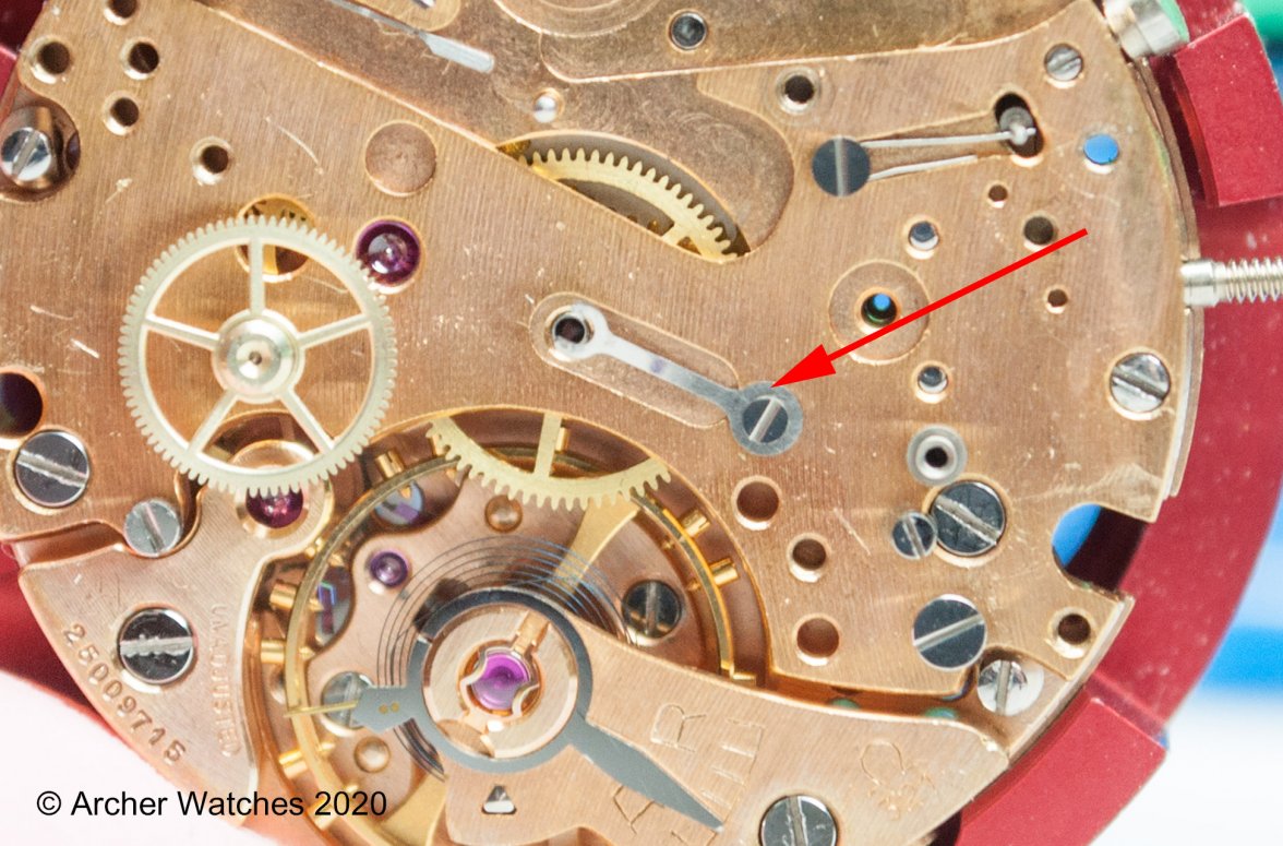
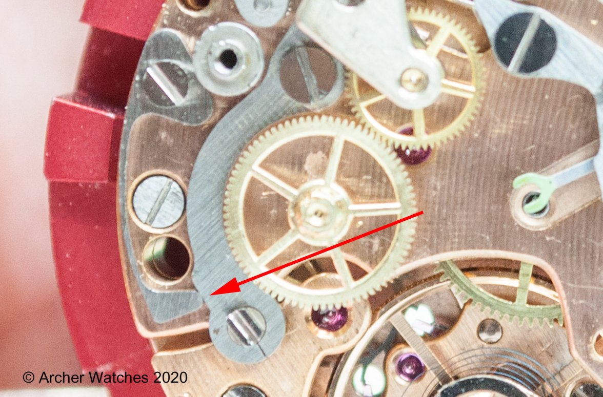
Sticking with the Cal. 321, this is the friction spring that is used for the chronograph wheel - this spring prevents the wheel and the central chronograph seconds hand from having that stuttering motion you sometimes see when it isn't adjusted properly:
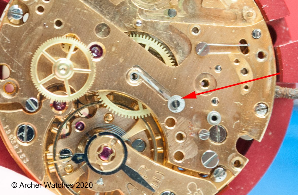
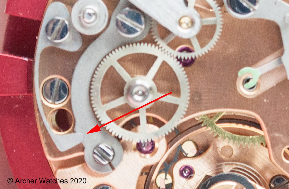
You can see that the spring is a forked shape at the spot where it would contact the underside of the chronograph wheel, and there is a relief machined into the wheel train and barrel bridge that is centered on the hole in the bridge where the center wheel can be seen. Here is an earlier version of the 321, and you can see this is a different design:
Here the friction spring doesn't have that forked end, and it's offset to only contact one side of the chronograph wheel. The relief machined into the bridge is also off center.
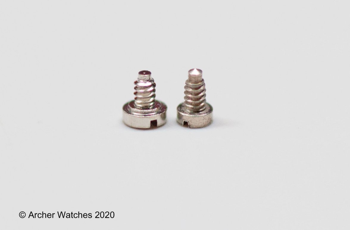
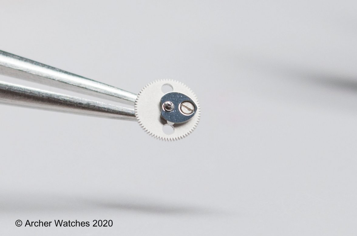
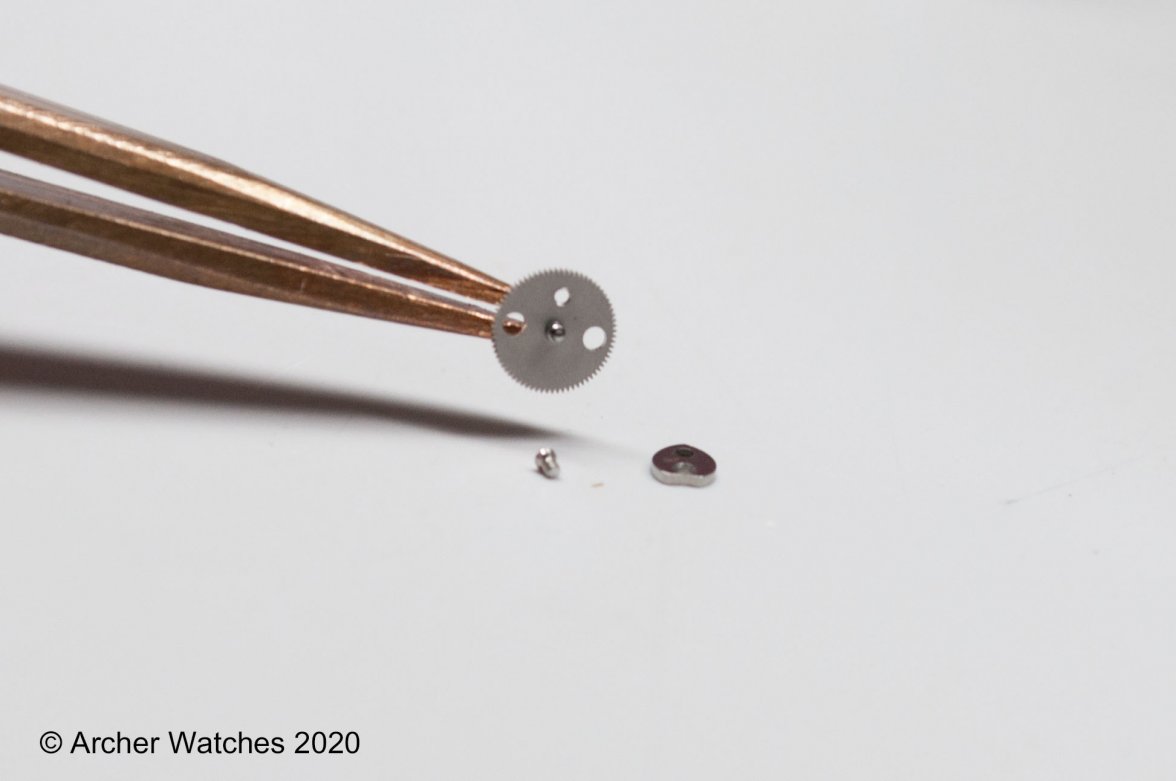
So the differences here aren't just what you can see in those photos, and here is a shot of the two screws that are used to hold these springs in place:
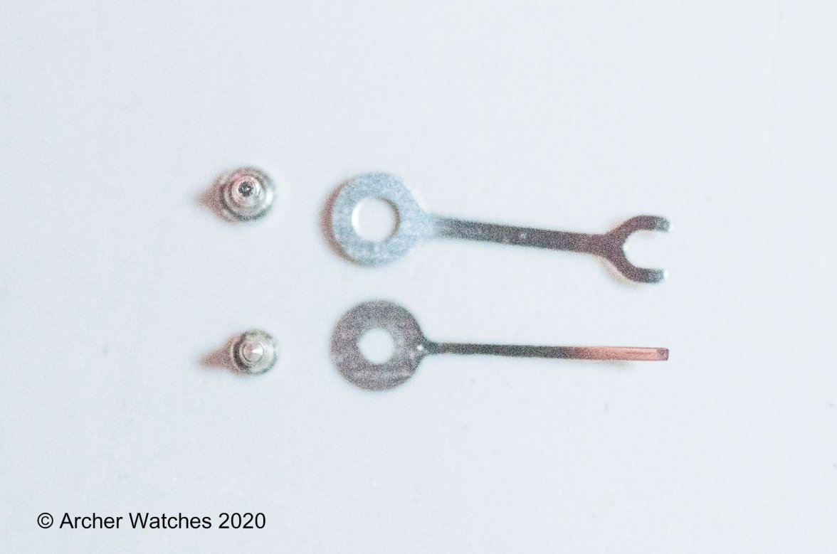
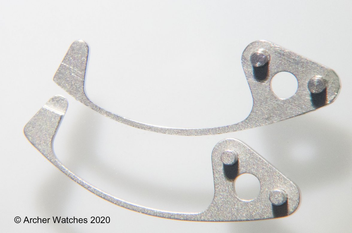
On the left is the screw that is used for the very first photo with the forked spring. You can see it has a small shoulder on it, and this means that when the screw is tight, the spring can float - in fact this is one of the first checks to be made on the chronograph mechanism as you are assembling it. The one on the right is for the older version, and the spring is held rigid when the screw is tight. Here are both screws and both springs:
What is sometimes difficult is to figure out why these changes were made. My guess here is that the forked spring does a better job at controlling the stutter of the wheel, and therefore the hand, and this design continues through the 861, 1861, and even the new 3861.
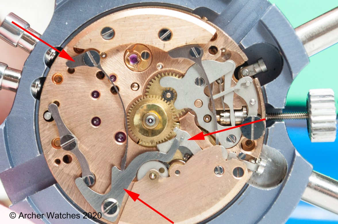
Here's a shot of the dial side of the same movement shown above in the first photo:
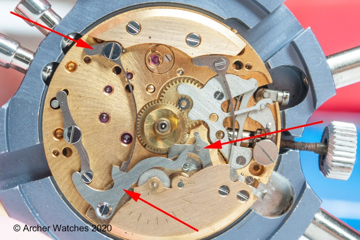
The lowest arrow points to the hour recorder stop lever - this is what prevents the hour recording wheel from turning when the chronograph is turned off. The upper left arrow points the the stop lever spring, and the right arrow points to the hour recorder hammer. Note the shapes of all three of these parts. Now let's look at the earlier movement:
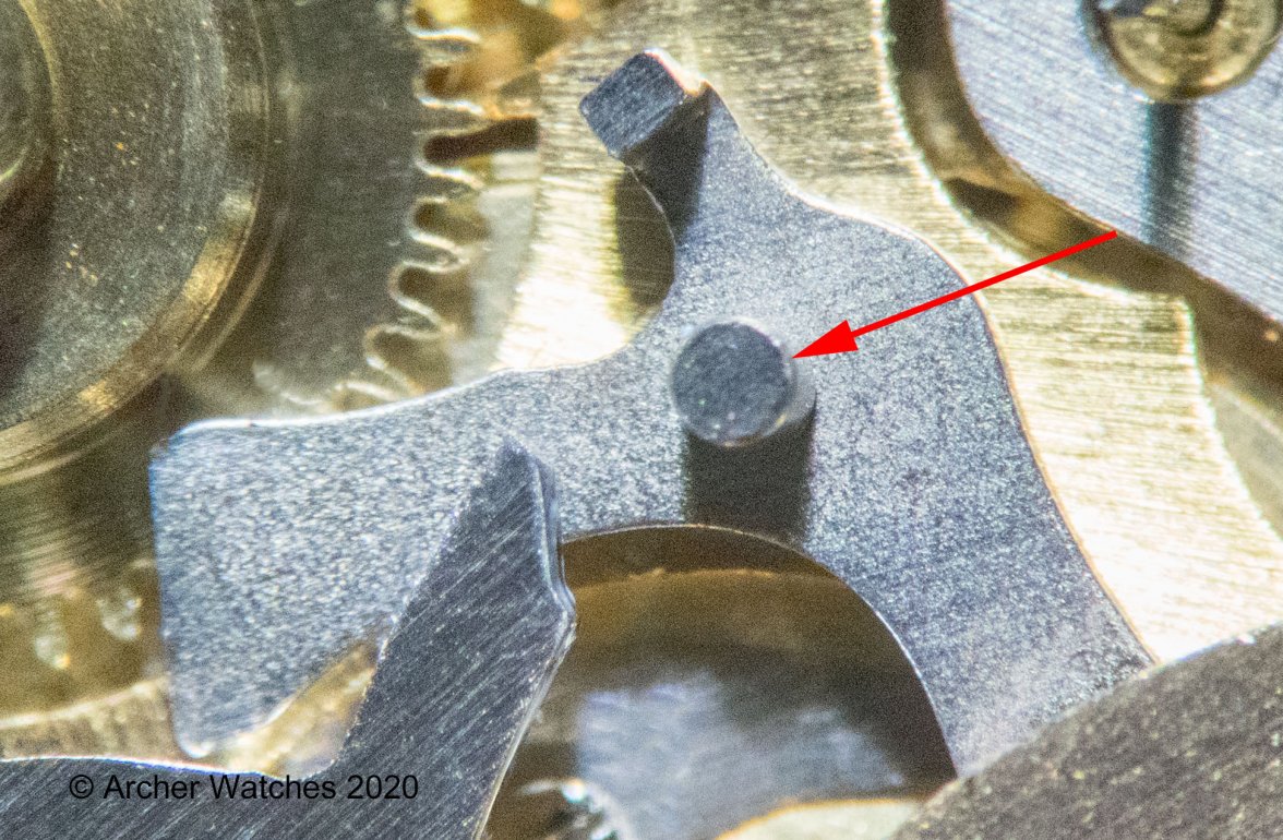
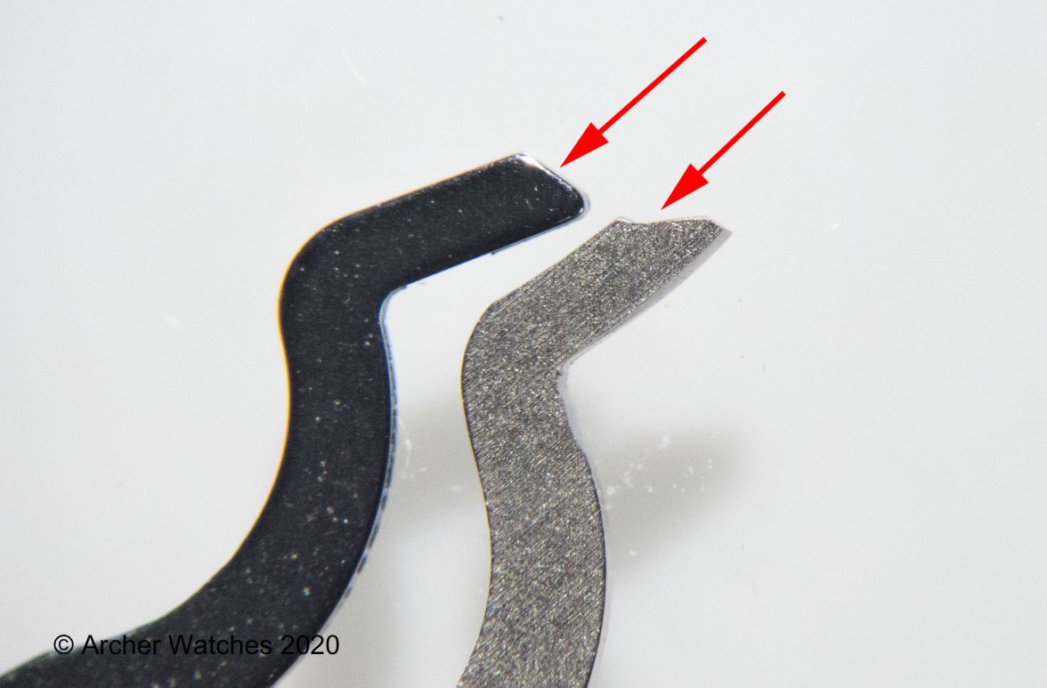
So you can see that the stop lever has a different shape in some areas. The area where the spring engages with the lever is deeper, and the part of the spring that meets the lever is larger and more squared. The end that interacts with the hammer is also quite differently shaped, and you can see that the pin on the hammer that contacts the lever (to move it out of the way when you reset) is much larger.
Closer view of the spring:
Closer view of the hammer:
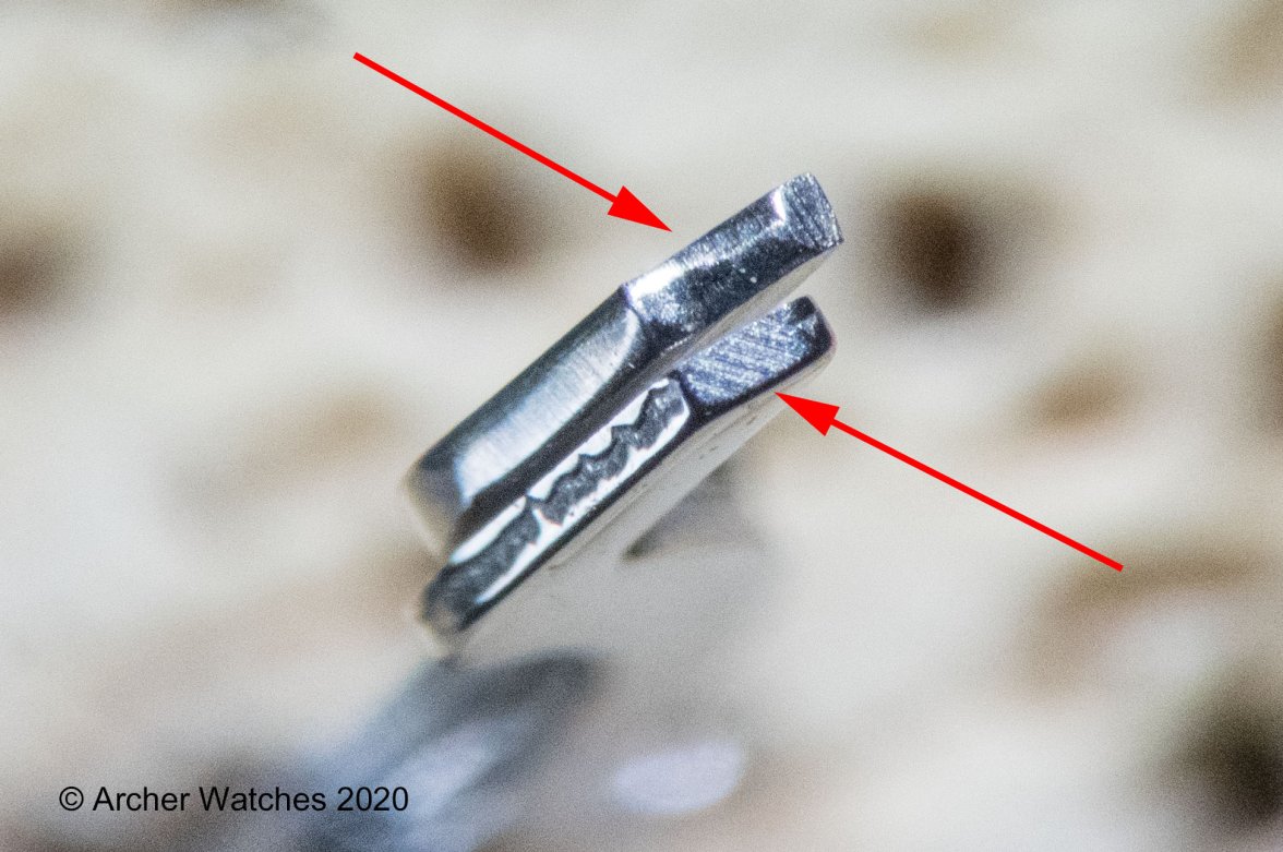
In the above photo you can see the shape of the stop lever where it contacts the larger pin of the hammer. Here is a view of both designs in profile - new stop lever on the left, and the early design on the right:
And here a view of the area where the pins contacts these same parts - new one on the right here:
So why were these changes made? Good question, because the older design looks far more robust than the new design does, so this one I don't have a good answer for.
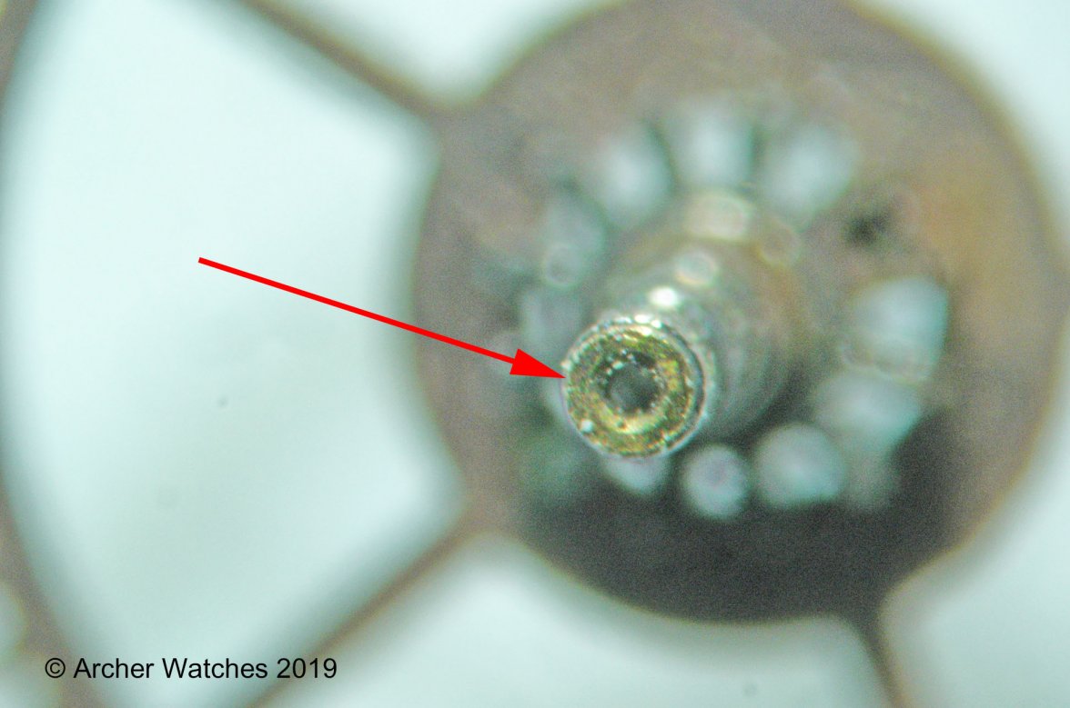
Turning now to something other than a chronograph, here a center wheel for a Cal. 550 series automatic. Note that in the end of the center wheel there is a brass bushing installed:
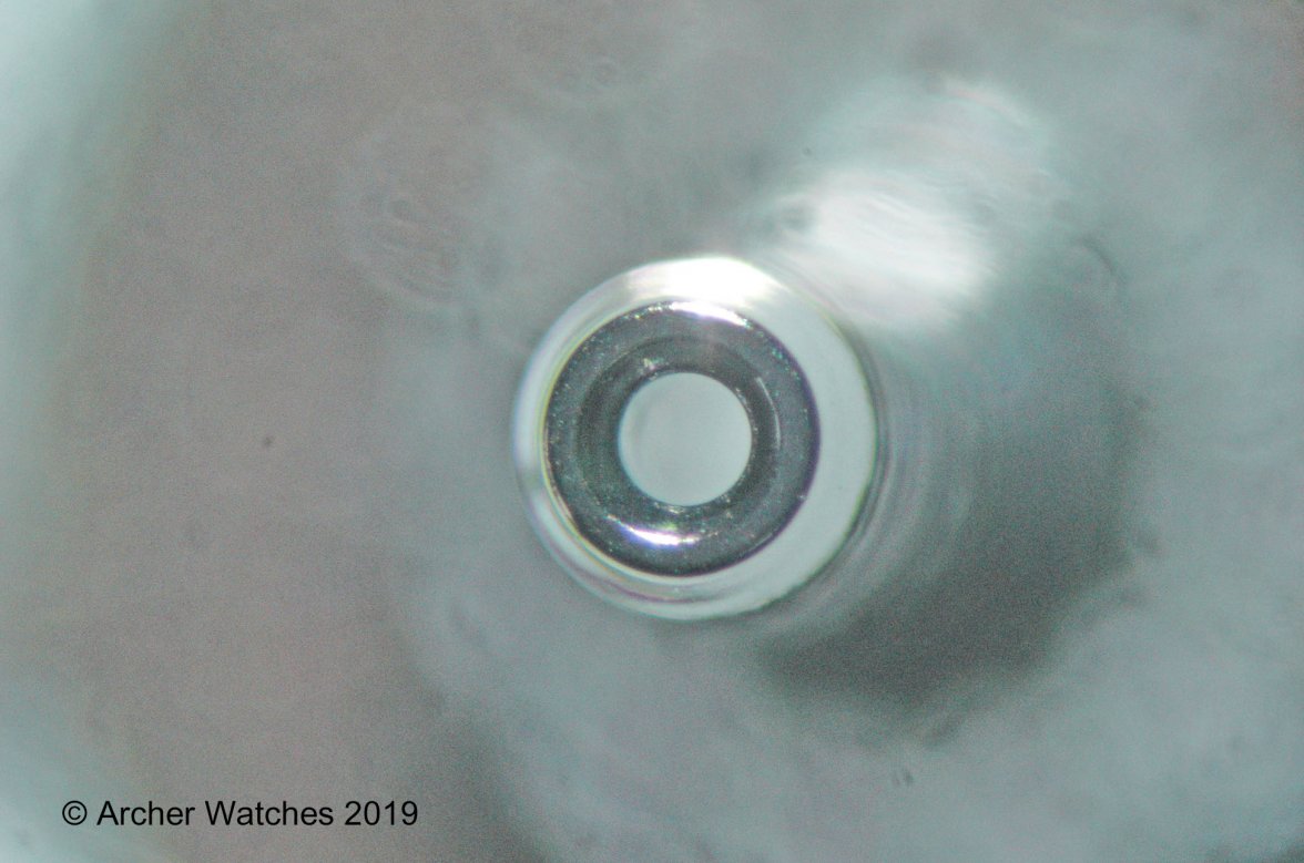
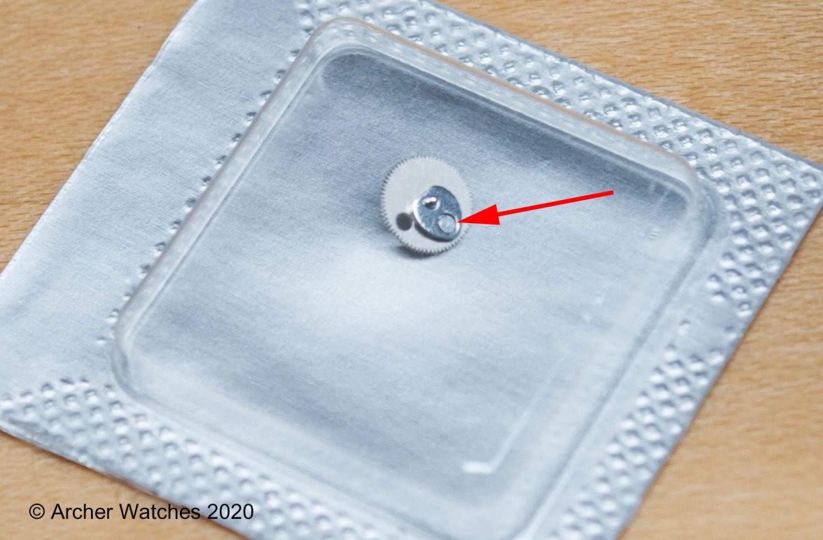
This bushing is what the center seconds pinion goes through, and it helps keep that pinion from wobbling all over the place. It is a press fitted part, and I've had numerous watches come in with this bushing either half falling out, or completely missing. Omega has redesigned this part to eliminate the separate bushing entirely, and now is is integrated right into the shaft of the wheel:
This change is considered a mandatory upgrade by Omega, so when a watch comes in with the old style, they want it upgraded to the new style to prevent failures down the road.
I'll post more examples when I have time, but what I wanted to illustrate is that movement designs are not static, and things are always being tweaked for various reasons. Some could be for quality issues, others for cost savings, but the designs many think of as being constant, really are not in many ways.
Cheers, Al
