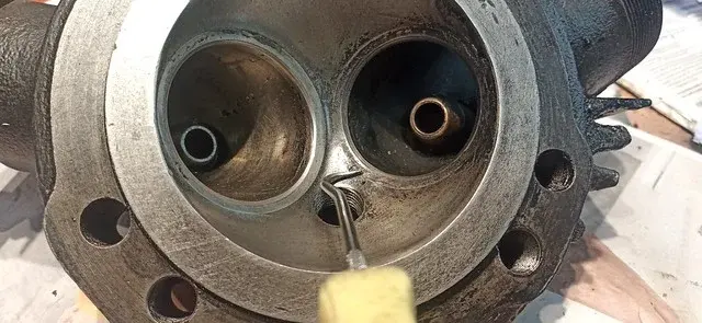
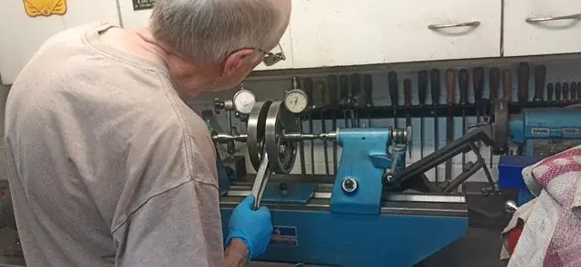
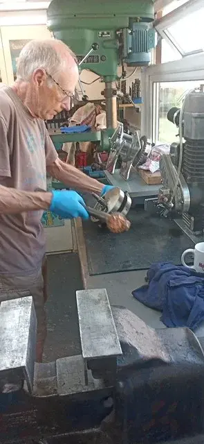
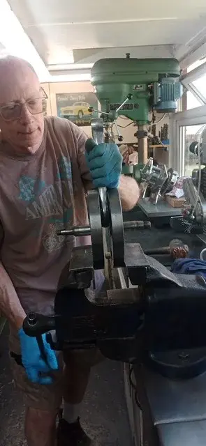
For someone with the same issues as Arthur Dent, I do seem to spend a lot of Thursdays in the workshop....
Decided yesterday to stop faffing and get on with some stuff.
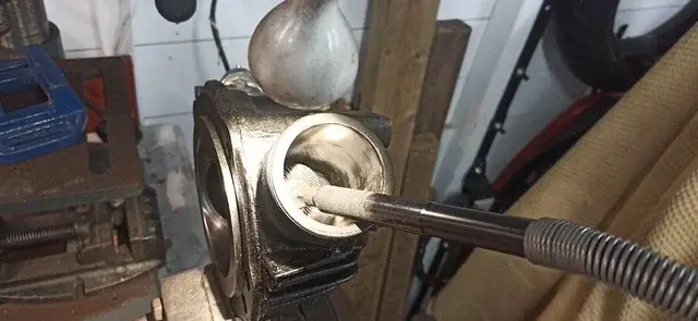
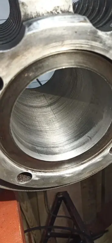
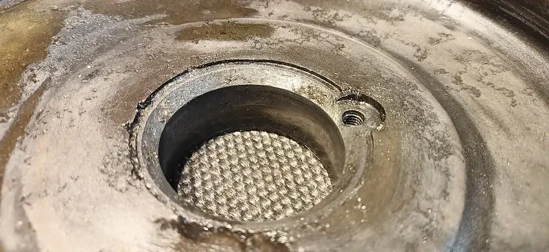
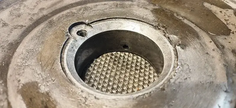
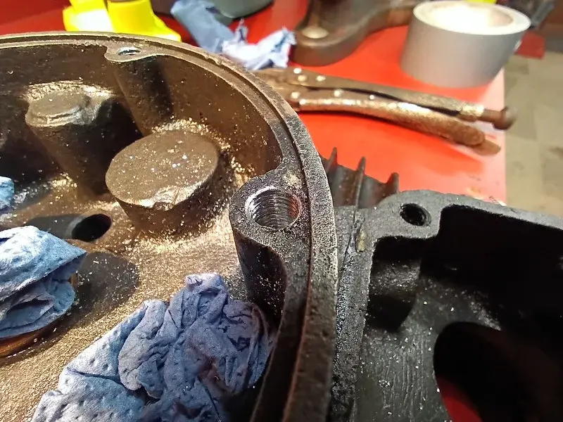
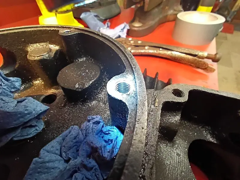
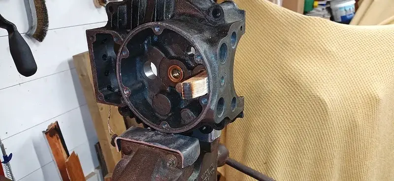
First, I cleaned up the drive-side crank case where the main crank bearing liner was removed:
Before.
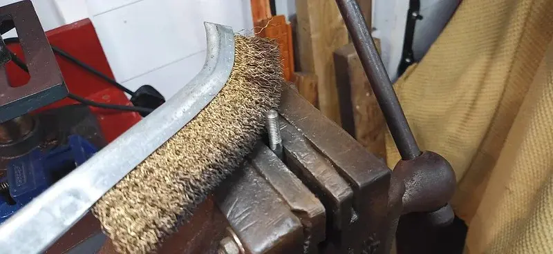
After a few minutes with a brass brush and a wipe down
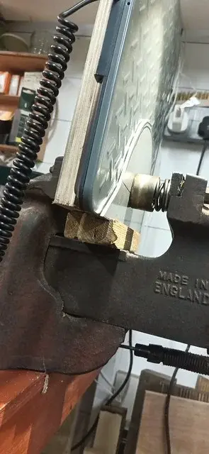
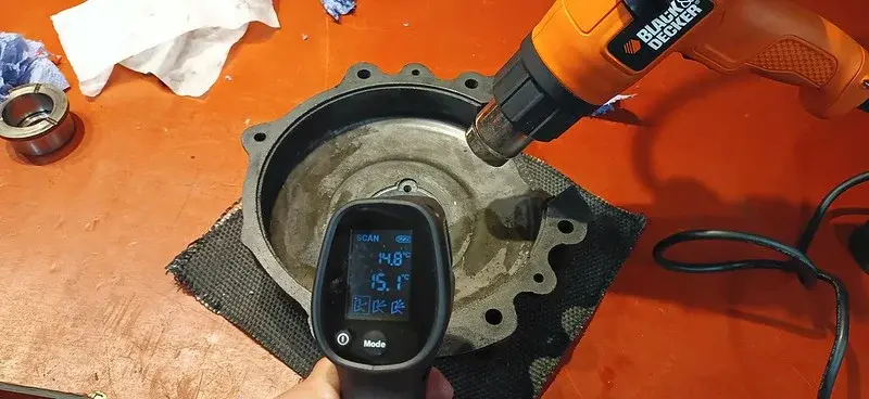
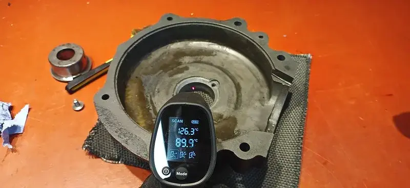
I rigged up the hot-air blower in an articulated grabber (a digital tablet holder in fact), and took a preparatory reading
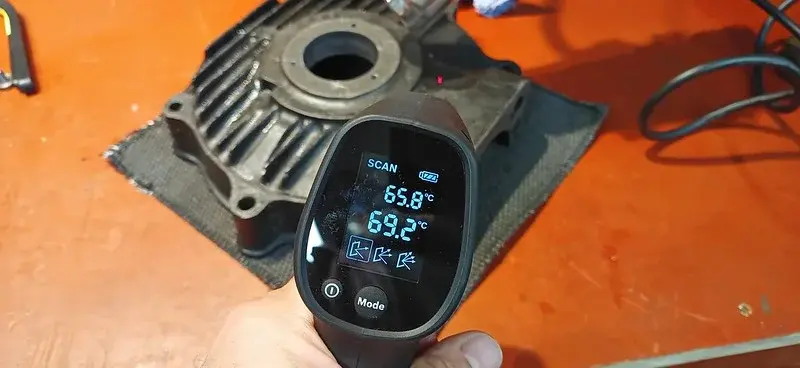
After only a few minutes I turned it over to get a good spread of heat:
Then I popped inside and retrieved the new liner from the freezer, where it had been hibernating for a few months....
That's the OLD bearing liner in the background of the photos.
When I got back, the temperature was even higher than this....
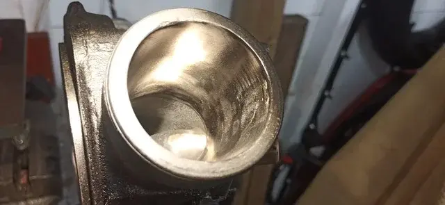
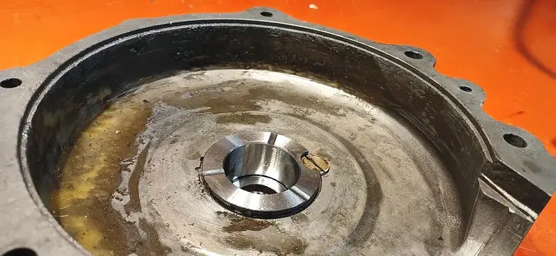
The inside was a little cooler after I took the heat off:
The new liner literally fell straight in, I was so surprised I didn't even remember to give it a tap, it didn't need it.
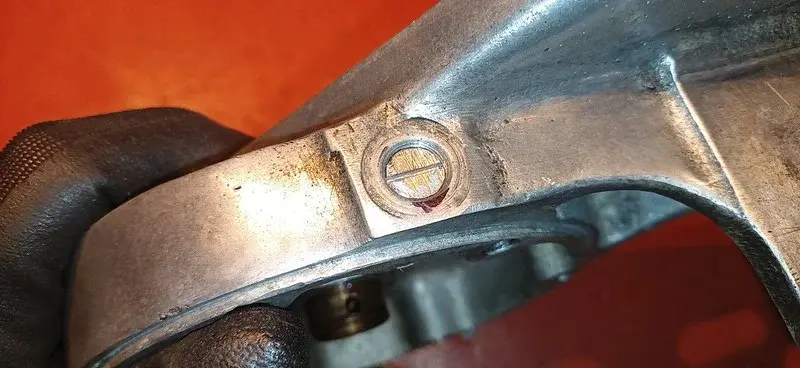
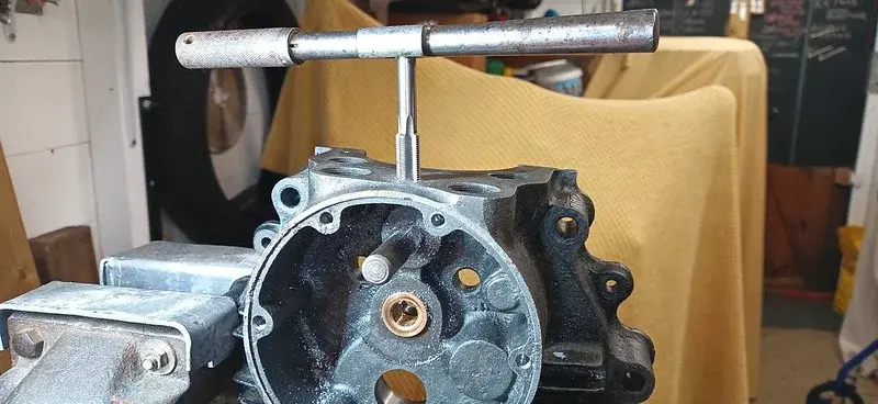
The little locating screw went straight in too.
Light at the end of the tunnel!
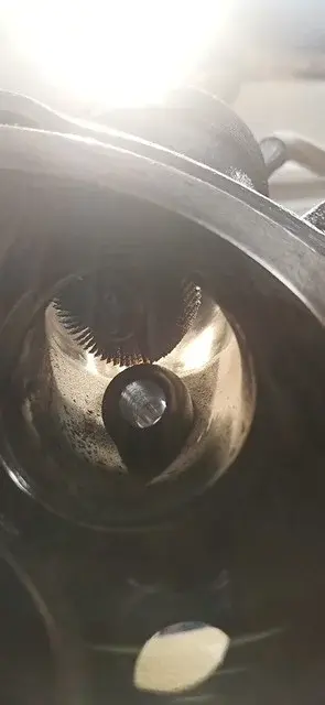
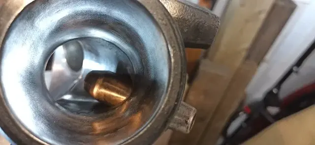
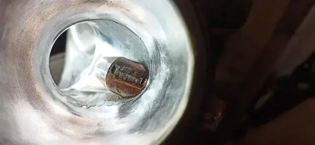
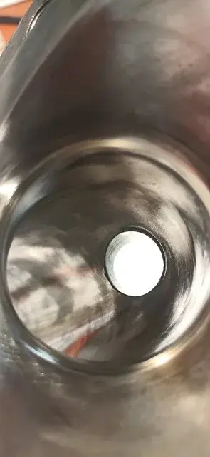
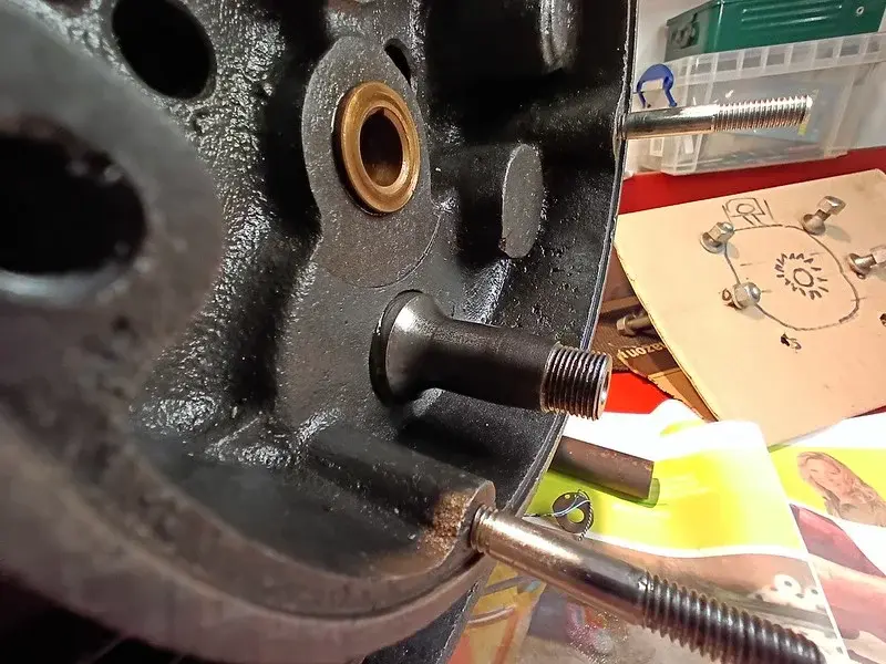
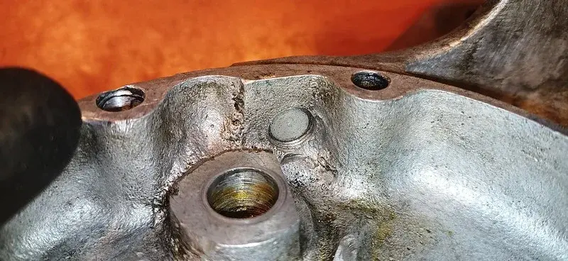
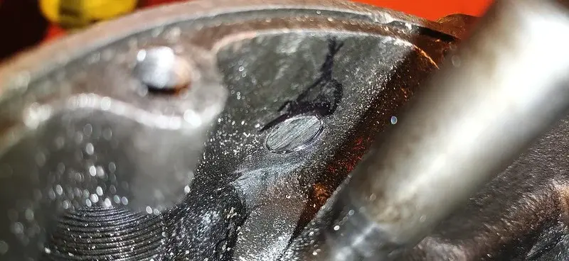
This is the "feed" for oil to the main crank bearing....
While it cooled off, I pondered what to do next..... then decided to go for it and dug out the new bearing cages and pins.
oh, and the grease.... LOTS of grease!
To be honest, I think I used more grease just on these bearings in ten minutes than I've used in any single year of working on bikes....
For some reason the original size roller pins aren't made any more so the accepted practise is to use 2 pins for each slot in the cage, and alternate the positioning - as you can see in the photo.
Almost as soon as I'd taken that pic and was pondering on the pins: I realised: hang on: the old pins I took off are the OLD ones! I actually have the proper old full-length bearing pins... a complete set! But, given that I have no idea just HOW old they are, I decided to stick with the fresh ones.
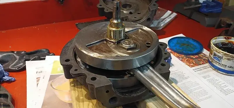
So - the cases went together relatively easily for the dry-fitting, to see what the crank end-float is:
Crank pushed fully to the left:
Crank pushed fully to the right:
I measured the difference using a micrometer tail and it appears to be a movement of about 0.065" - I measured a few times, obvously, and I think the extremes were 0.078" down to 0.050" - so the consensus is about 0.065.
I checked what I'd written down earlier and read "crank end float : 0.12" - 0.15" ".
Hang on.... (I thought).
How can my end float be LESS than the desired?? Did the Liner not go in properly?? Have I got to take the liner out again?? fucksticks!!
So - I ended up having a quick call with the Guru, and while I was talking to him I took another look at the book....
which read:
Crank End Float : 0.012" - 0.015".
GAAAAH!!!! what a muppet!!! I apologised profusely to the Guru for wasting his time, he was very nice about it and we had a nice chat about things anyway, and I got on with it whilst kicking myself!!
In my defense - I'm a metric kid, I've no concept of what thousands of an inch "look" like!
I agreed with the Guru that all the crank needs is some gentle shimming (phnar) and dug out the collection of shims I've got : some new, (iirc supplied by the Guru) and some from the original build.
0.050, 0.040, 0.023(*2), 0.020, 0.010.
So - with any luck - the 0.023 pairing should be exactly what I need!
😁
Required thickness of shims: 0.065" - 0.015" = 0.05".
Desired shim width if using 2 shims : 0.05" / 2 = 0.025"
I can also potentially use the 0.010 and 0.020 to get it a bit tighter if required. but I'll have an afternoon of tinkering with that no doubt!.
I'm probably going to reassemble the cases again, dry, and double check that end-float, before deciding fully, but the crank looked pretty central so that should do the job.
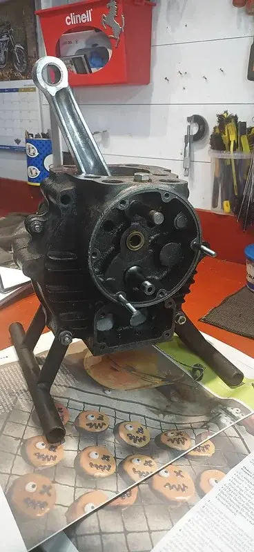
This whole job was made MASSIVELY easier because I found a pair of legs for the engine last time I was in Dad's workshop:
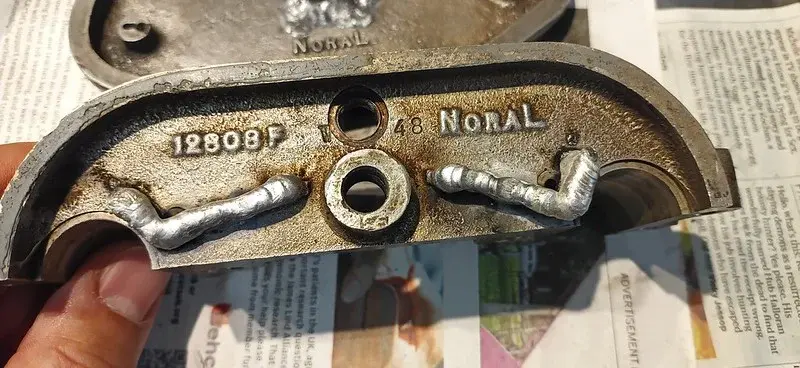
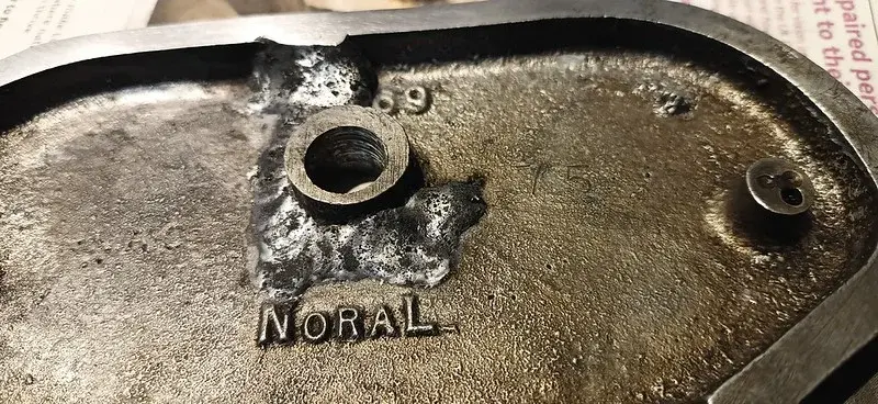
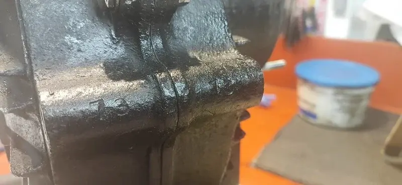
While I as pondering things I also noticed that the cases have another set of numbers on the rear faces :
I have no idea what these would be (they're not the engine numbers, those are on the front, on the rhs), and I'm tickled somewhat that they match, given that the cases are from totally different sources!
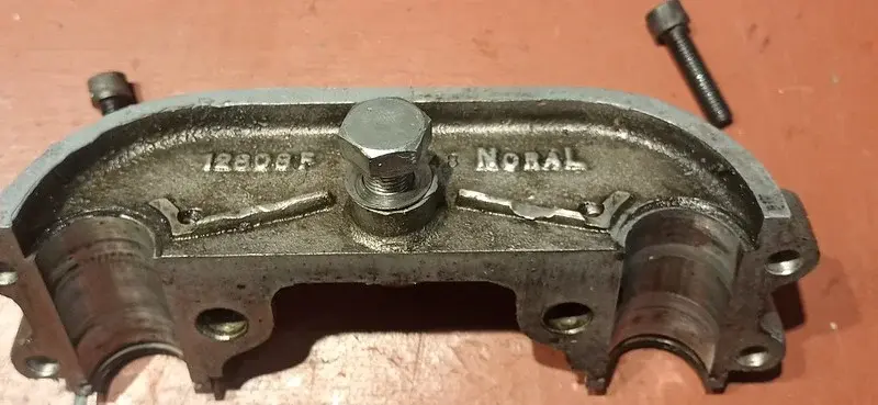
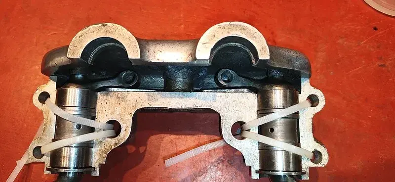
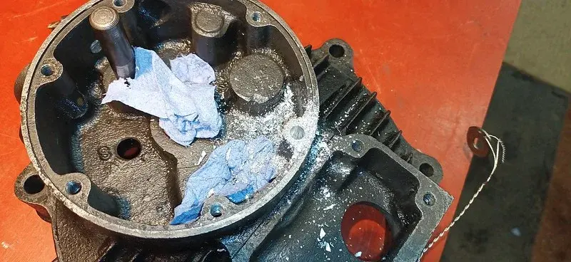
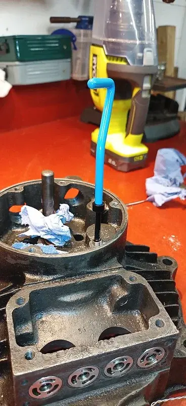
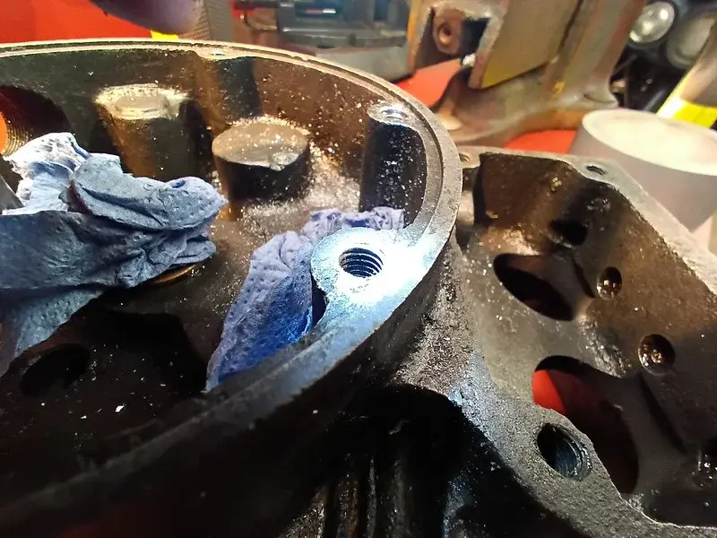
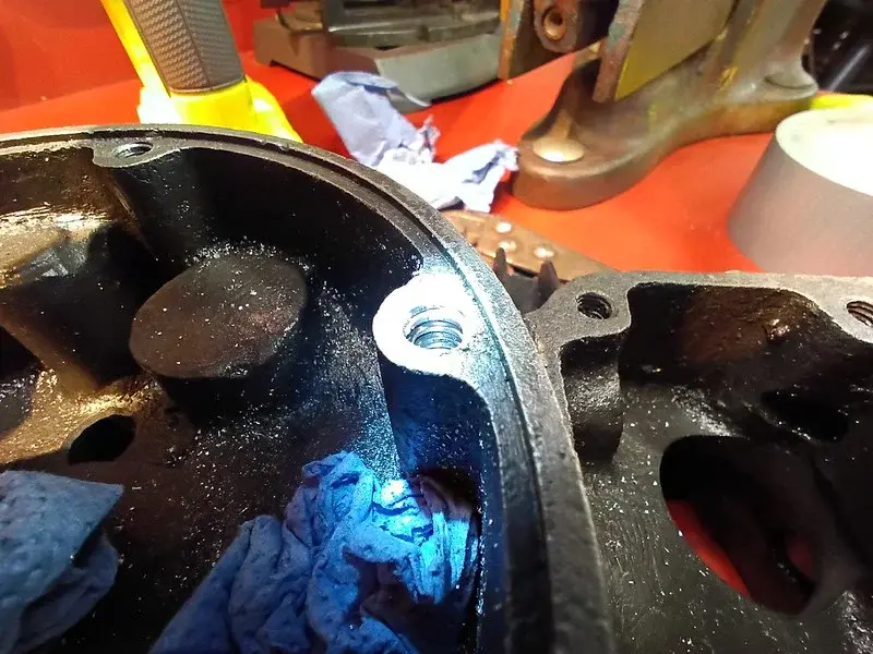
After I'd dissassembled the crank again to put it out of the way, I figured I'd make a start on the rocker box...
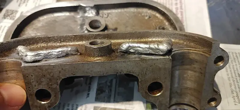
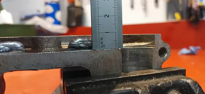
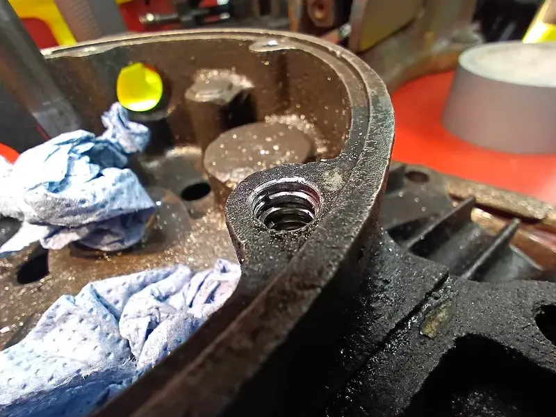
Measuring up the excess that needs to come off...
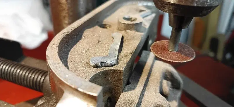
Answer: a lot. These little shelves are supposed to be about 3mm high.....
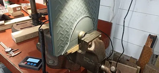
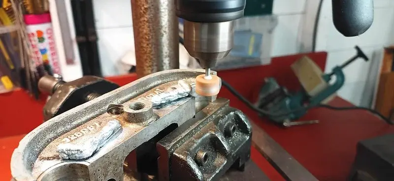
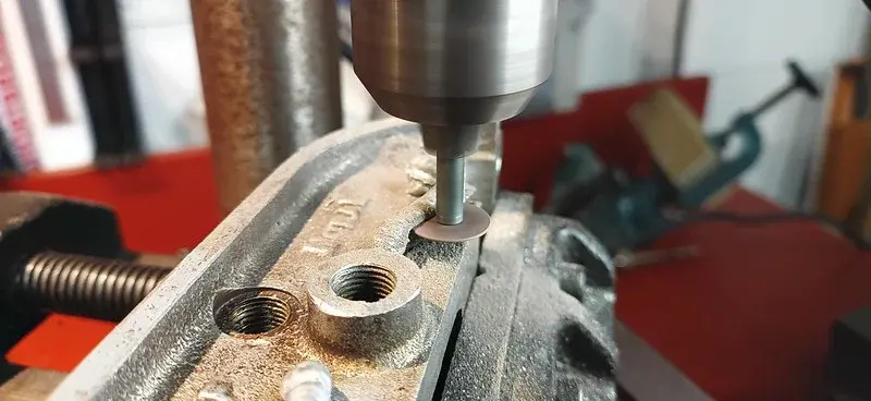
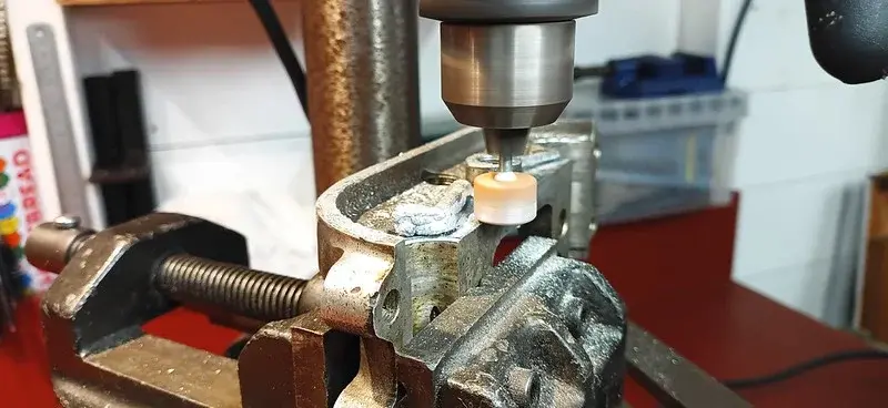
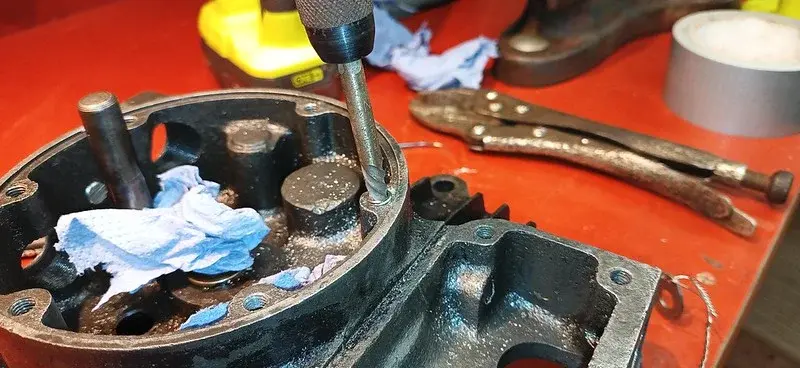
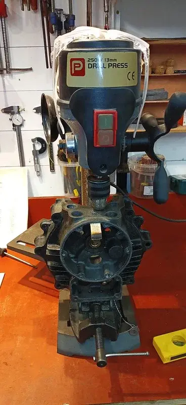
Setting up the ersatz "single-axis-milling-machine" (dremel grindstone in the pillar drill!)
I used the grind stone first just to test the concept, and it worked well.
So I dug out a pot of cutting wheels.
😁
I should state that there was a good long session of faffing with a bubble level to quadruple check that the everything was as flat as possible (the drill stand, the drill plate, the clamp, the workpiece, etc etc etc)
The main faff with it is replacing the cutting wheels every few minutes, but the rod that holds the wheel is chamfered about half-way down, so it's actually very easy to put it back into the drill in exactly the same place each time: with the chamfer butted up against the outer face of the drill-clamp jaws.
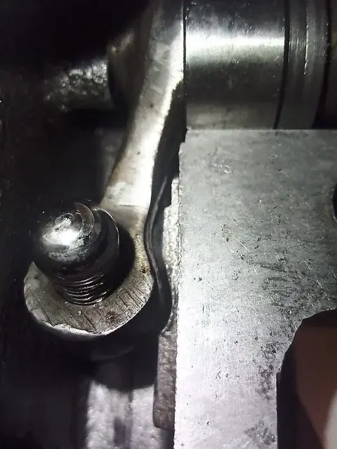
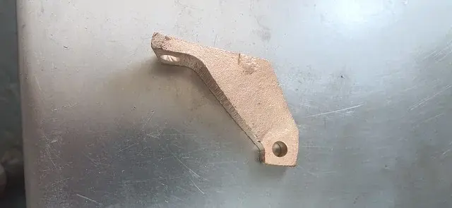
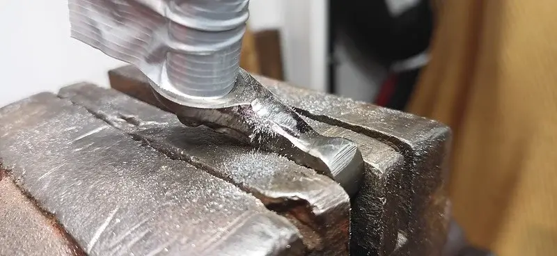
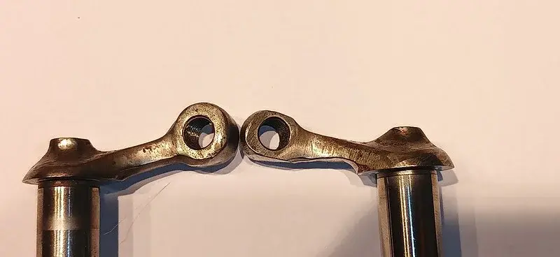
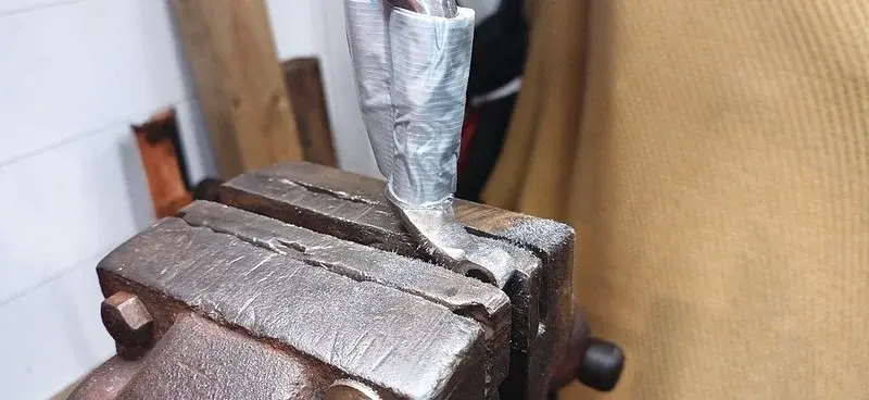
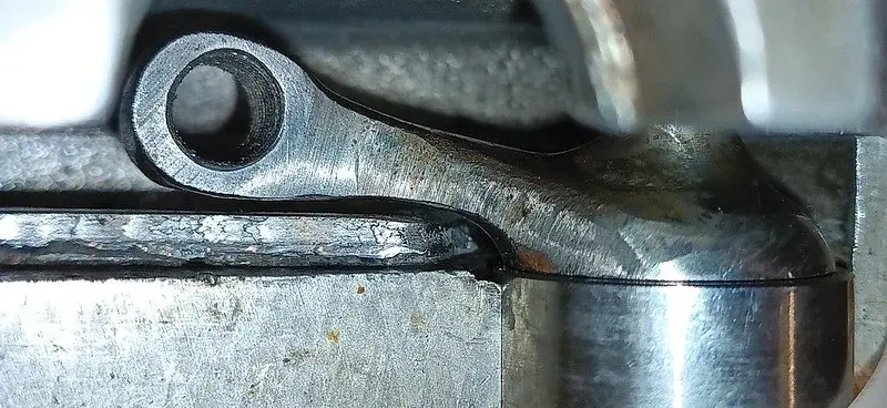
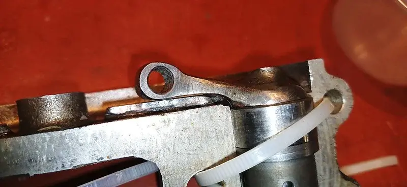
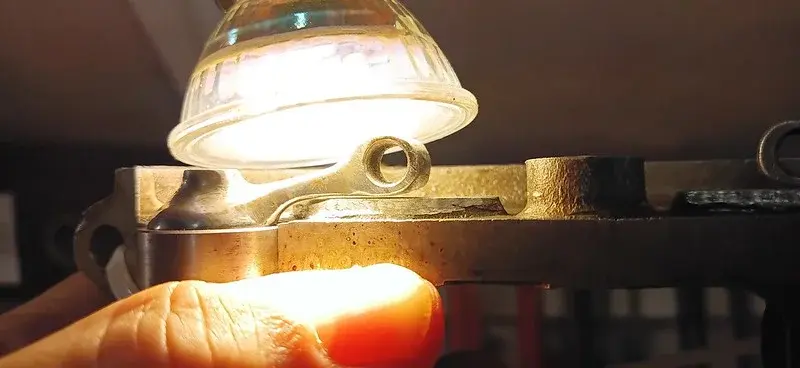
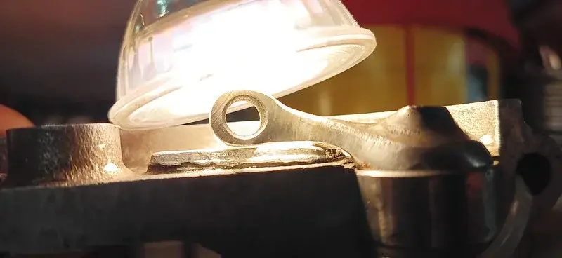
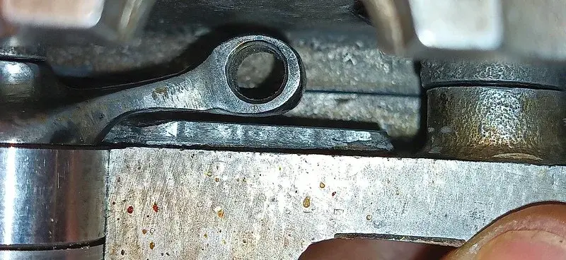
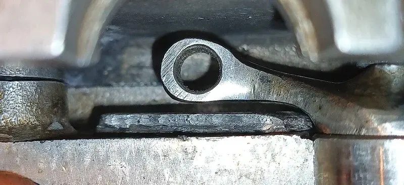
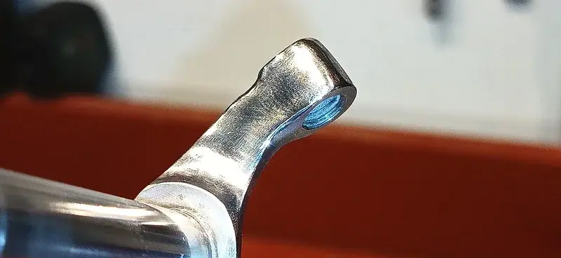
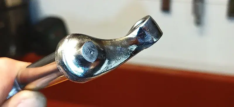
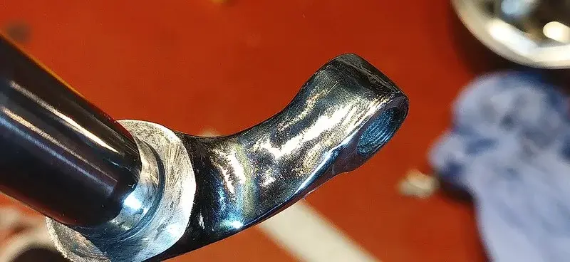
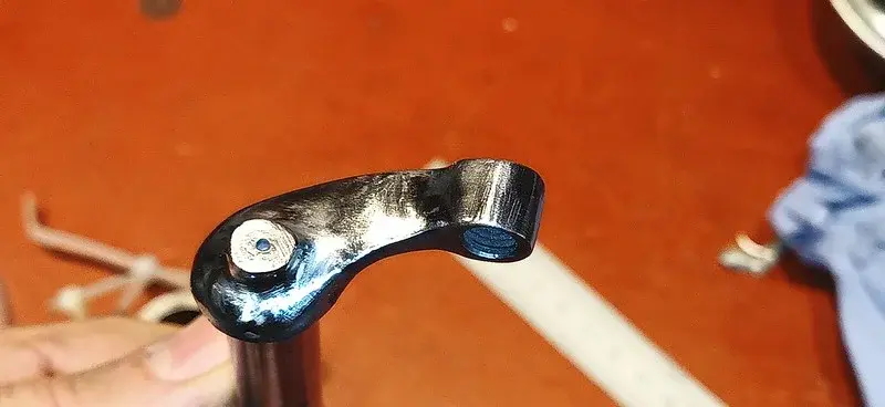
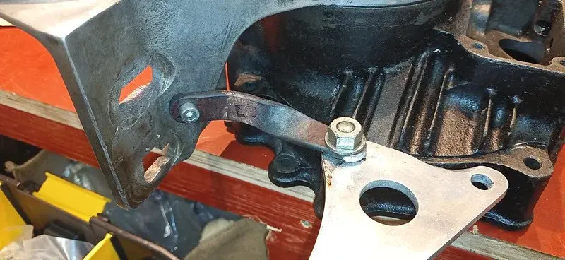
I got the first shelf (the exhaust side as it happens) cut down somewhat roughly and put the rocker arm together so I could check it against the shelf. There was still a of interference, so I decided to have a go at the rocker arm as well :
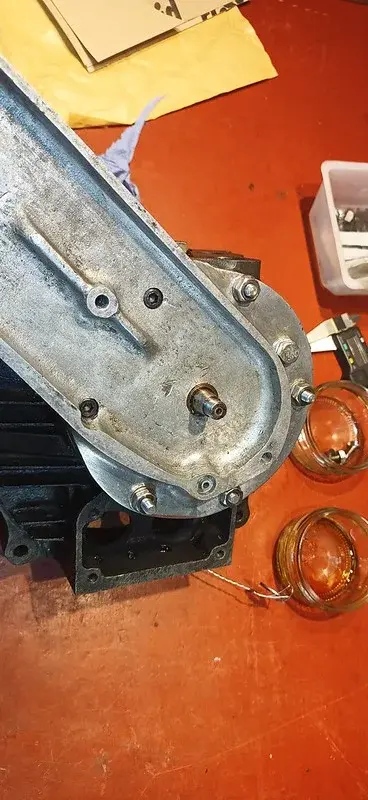
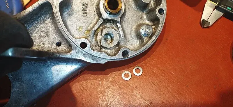
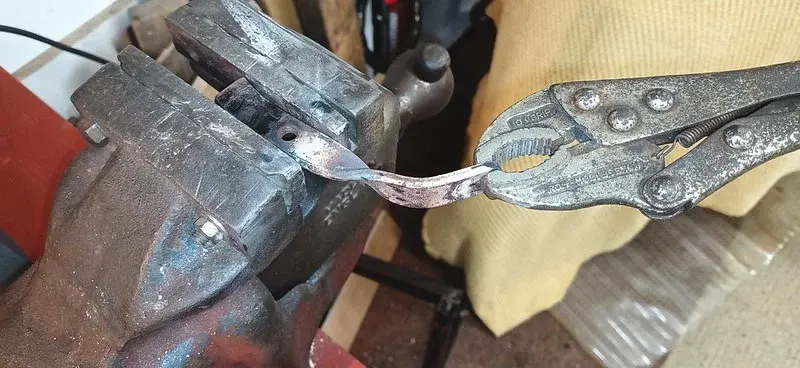
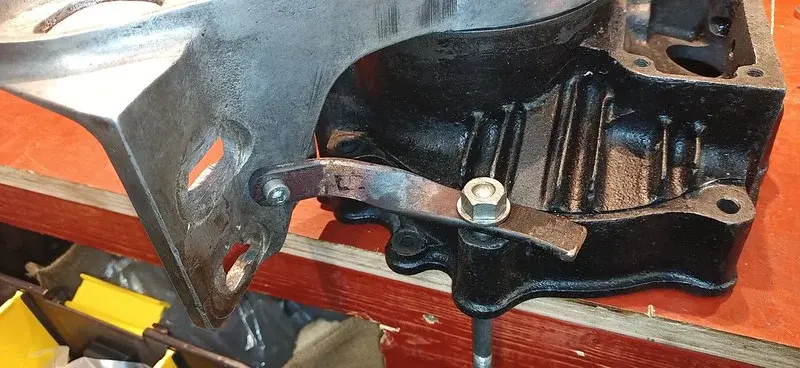
This was filing down the sides of the arm, to help it clear the oil-gallery/shelf. I also took it over to the grinder and shaved off quite a bit of the metal from around the bolthole where the ball-fitting is fitted.
I'll take more photos of the rocker arm next time I'm in there. Still a lot to do, but some good progress made I think.
